OPERATION | ||
|
|
|
V300 SETTINGS
Read and understand the V300 Instruction Manual before attempting to use the V300/MIG Pulser system. Also refer to figure A.2 in the Installation chapter.
The V300 must be set to the TIG Mode when using the MIG Pulser. This is because pulse welding is a current controlled process, not a constant voltage process like straight GMAW. By using the GTAW position, the V300 is placed in a current control mode, and the Arc Force/Inductance control is made inactive.
The Wire Feeder Voltmeter Switch on the back of the V300 must be set to the
The V300 Local/Remote Switch must be set to Remote Control. This allows the MIG Pulser to control the V300 output. The Output Control on the V300 is not func- tional in the Remote Control mode.
Other V300 settings should be made according to the installation conditions and the wire feeders used.
MIG PULSER CONTROLS AND SETTINGS
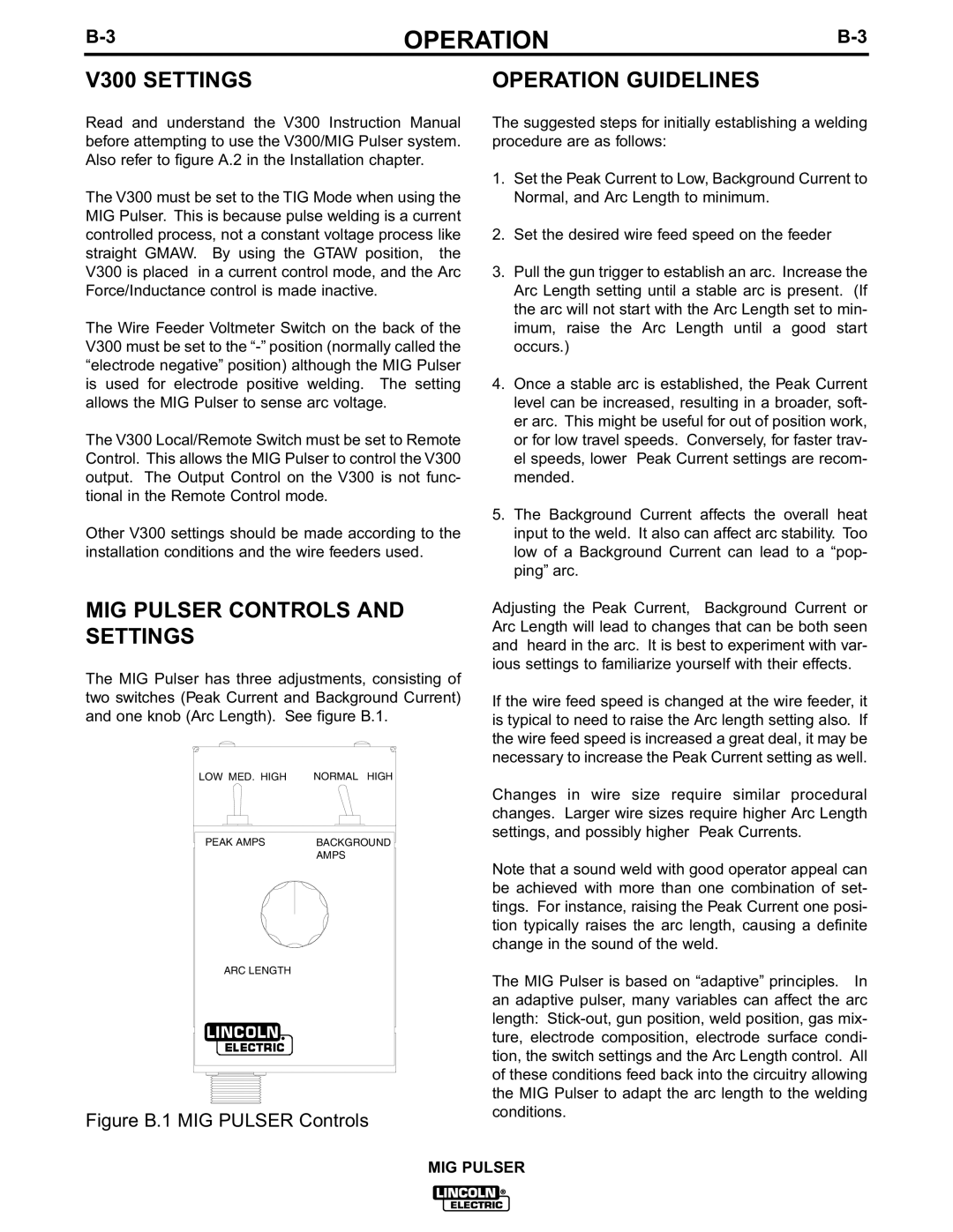
The MIG Pulser has three adjustments, consisting of two switches (Peak Current and Background Current) and one knob (Arc Length). See figure B.1.
LOW MED. HIGH | NORMAL HIGH |
PEAK AMPS | BACKGROUND |
| AMPS |
ARC LENGTH
Figure B.1 MIG PULSER Controls
OPERATION GUIDELINES
The suggested steps for initially establishing a welding procedure are as follows:
1.Set the Peak Current to Low, Background Current to Normal, and Arc Length to minimum.
2.Set the desired wire feed speed on the feeder
3.Pull the gun trigger to establish an arc. Increase the Arc Length setting until a stable arc is present. (If the arc will not start with the Arc Length set to min- imum, raise the Arc Length until a good start occurs.)
4.Once a stable arc is established, the Peak Current level can be increased, resulting in a broader, soft- er arc. This might be useful for out of position work, or for low travel speeds. Conversely, for faster trav- el speeds, lower Peak Current settings are recom- mended.
5.The Background Current affects the overall heat input to the weld. It also can affect arc stability. Too low of a Background Current can lead to a “pop- ping” arc.
Adjusting the Peak Current, Background Current or Arc Length will lead to changes that can be both seen and heard in the arc. It is best to experiment with var- ious settings to familiarize yourself with their effects.
If the wire feed speed is changed at the wire feeder, it is typical to need to raise the Arc length setting also. If the wire feed speed is increased a great deal, it may be necessary to increase the Peak Current setting as well.
Changes in wire size require similar procedural changes. Larger wire sizes require higher Arc Length settings, and possibly higher Peak Currents.
Note that a sound weld with good operator appeal can be achieved with more than one combination of set- tings. For instance, raising the Peak Current one posi- tion typically raises the arc length, causing a definite change in the sound of the weld.
The MIG Pulser is based on “adaptive” principles. In an adaptive pulser, many variables can affect the arc length:
MIG PULSER