SAE400 & SAE400 WELD’N AIR
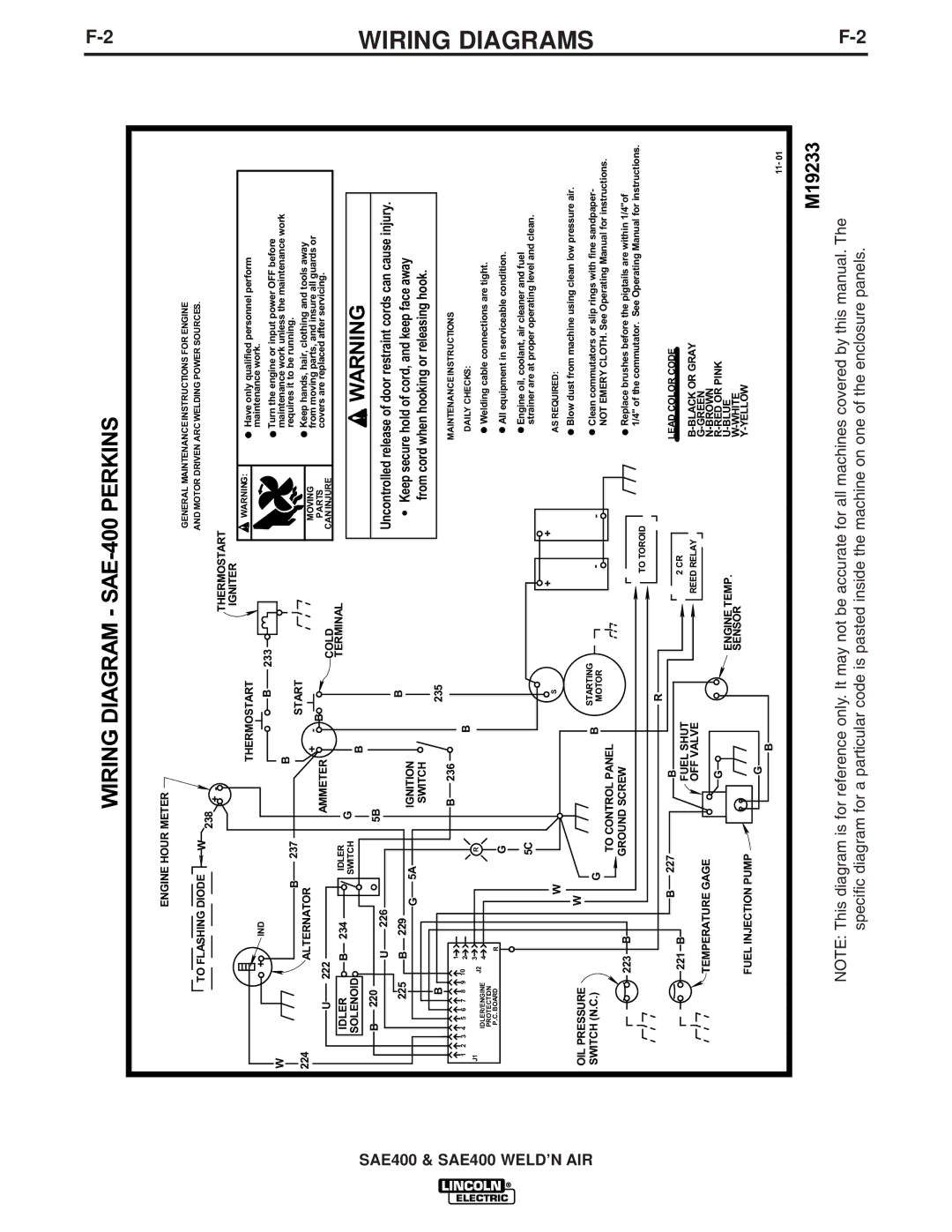
WIRING DIAGRAM - SAE-400 PERKINS
ENGINE HOUR METER
|
|
|
|
|
|
|
|
|
|
|
| GENERAL MAINTENANCEINSTRUCTIONS FOR ENGINE | |
| TO FLASHING DIODE | W |
|
|
|
|
|
| AND MOTOR DRIVEN ARC WELDING POWER SOURCES. | ||||
| 238 | + | - |
|
|
|
|
| |||||
|
|
|
|
|
|
|
|
| THERMOSTART |
| |||
|
|
|
|
|
|
|
|
|
|
| |||
|
|
|
|
|
|
|
|
|
|
|
| ||
|
|
|
|
|
|
|
|
|
|
| IGNITER |
|
|
|
|
|
|
|
|
|
| THERMOSTART |
| WARNING: | Have only qualified personnel perform | ||
|
|
|
|
|
|
|
|
|
| ||||
|
| + | IND |
|
|
|
|
|
| B | 233 |
| maintenance work. |
|
|
|
|
|
|
|
|
| Turn the engine or input power OFF before | ||||
W |
|
|
|
|
|
|
|
|
|
| |||
|
|
|
|
|
|
|
|
|
|
|
| ||
|
|
|
|
|
|
| B |
|
|
|
| maintenance work unless the maintenance work | |
|
|
| B |
| 237 |
|
|
|
|
|
| requires it to be running. | |
|
|
|
|
|
|
|
| START |
|
| |||
224 |
|
|
|
|
|
|
|
|
| Keep hands, hair, clothing and tools away | |||
| ALTERNATOR |
|
|
|
|
|
|
|
| ||||
|
|
|
|
| + | - |
|
| MOVING | ||||
|
|
|
|
|
|
|
| B |
| from moving parts, and insure all guards or | |||
| U | 222 |
|
|
| AMMETER |
| COLD | PARTS | covers are replaced after servicing. | |||
|
|
|
|
|
|
|
|
| CAN INJURE |
| |||
IDLER | B | 234 | IDLER | G |
|
|
|
| TERMINAL |
| WARNING | ||
SWITCH |
|
|
|
|
|
| |||||||
SOLENOID |
|
| B |
|
|
|
| ||||||
|
|
|
|
|
|
|
|
| |||||
B | 220 | U | 226 |
|
| 5B |
|
|
|
|
| Uncontrolled release of door restraint cords can cause injury. | |
|
|
|
|
|
|
|
| B |
| ||||
| 225 | B | 229 |
|
|
| IGNITION |
|
| Keep secure hold of cord, and keep face away | |||
| 5A |
|
|
|
|
| |||||||
|
|
| G |
|
|
|
|
| from cord when hooking or releasing hook. | ||||
|
|
|
|
|
|
| SWITCH |
|
|
| |||
| B |
|
|
|
|
|
|
|
| 235 |
|
|
|
|
| 1 |
|
|
|
| B 236 |
|
|
|
| MAINTENANCEINSTRUCTIONS | |
|
|
|
|
|
|
|
|
|
|
|
|
| |
1 2 3 4 5 | 6 7 8 9 | 10 2 |
|
|
|
|
|
| B |
|
|
| DAILY CHECKS: |
J1 |
| 3 |
|
| R |
|
|
|
|
|
|
|
|
IDLER/ENGINE | J2 |
|
|
|
|
|
|
|
|
|
| Welding cable connections are tight. | |
4 |
|
|
|
|
|
|
|
|
|
| |||
PROTECTION |
|
|
|
|
|
|
|
|
|
|
|
| |
P.C. BOARD | R |
|
| G |
|
|
|
|
|
|
| All equipment in serviceable condition. | |
|
|
|
|
|
|
|
|
|
|
|
| ||
|
|
|
|
| 5C |
|
|
|
|
|
|
| Engine oil, coolant, air cleaner and fuel |
|
|
|
|
|
|
|
|
|
|
|
| strainer are at proper operating level and clean. | |
|
|
| W |
|
|
|
|
|
| S | + | + | AS REQUIRED: |
|
|
|
|
|
|
|
|
|
|
| |||
|
|
|
|
|
|
|
|
|
|
|
| ||
OIL PRESSURE |
| W |
|
|
|
|
|
|
|
|
| Blow dust from machine using clean low pressure air. | |
|
|
|
|
|
|
|
|
|
|
| |||
|
|
|
|
|
|
|
| STARTING |
| Clean commutators or slip rings with fine sandpaper- | |||
SWITCH (N.C.) |
| G |
|
|
|
| B | - | |||||
| TO CONTROL PANEL | MOTOR | - | NOT EMERY CLOTH. See Operating Manual for instructions. | |||||||||
|
|
|
|
|
|
|
|
|
| ||||
|
| 223 | B |
| GROUND SCREW |
|
|
|
| Replace brushes before the pigtails are within 1/4"of | |||
|
|
|
|
|
|
|
|
|
|
| |||
|
|
|
|
|
|
|
|
|
|
| TO TOROID | 1/4" of the commutator. See Operating Manual for instructions. | |
|
|
|
|
|
|
|
|
|
|
|
| ||
|
|
|
| 227 |
|
|
|
| R |
|
|
| |
|
| 221 | B |
|
| B |
|
|
|
| LEAD COLOR CODE | ||
|
| B |
|
|
|
| FUEL SHUT |
| 2 CR |
| |||
|
|
|
|
|
|
|
| OFF VALVE |
| REED RELAY |
| ||
|
| TEMPERATURE GAGE |
|
|
|
|
|
|
|
| |||
|
|
|
|
| G |
|
|
|
| ||||
|
|
|
|
|
|
|
|
|
| ENGINE TEMP. |
| ||
|
|
|
|
|
|
|
|
|
|
|
| ||
|
|
|
|
|
|
|
|
|
|
| SENSOR |
| |
|
| FUEL INJECTION PUMP |
|
|
|
|
|
|
| ||||
|
|
|
| G |
|
|
|
|
| ||||
|
|
|
|
|
|
|
|
|
|
|
|
| |
|
|
|
|
|
|
|
| B |
|
|
|
| 11- 01 |
|
|
|
|
|
|
|
|
|
|
|
|
| |
M19233
NOTE: This diagram is for reference only. It may not be accurate for all machines covered by this manual. The specific diagram for a particular code is pasted inside the machine on one of the enclosure panels.