INSTALLATION | ||
|
|
|
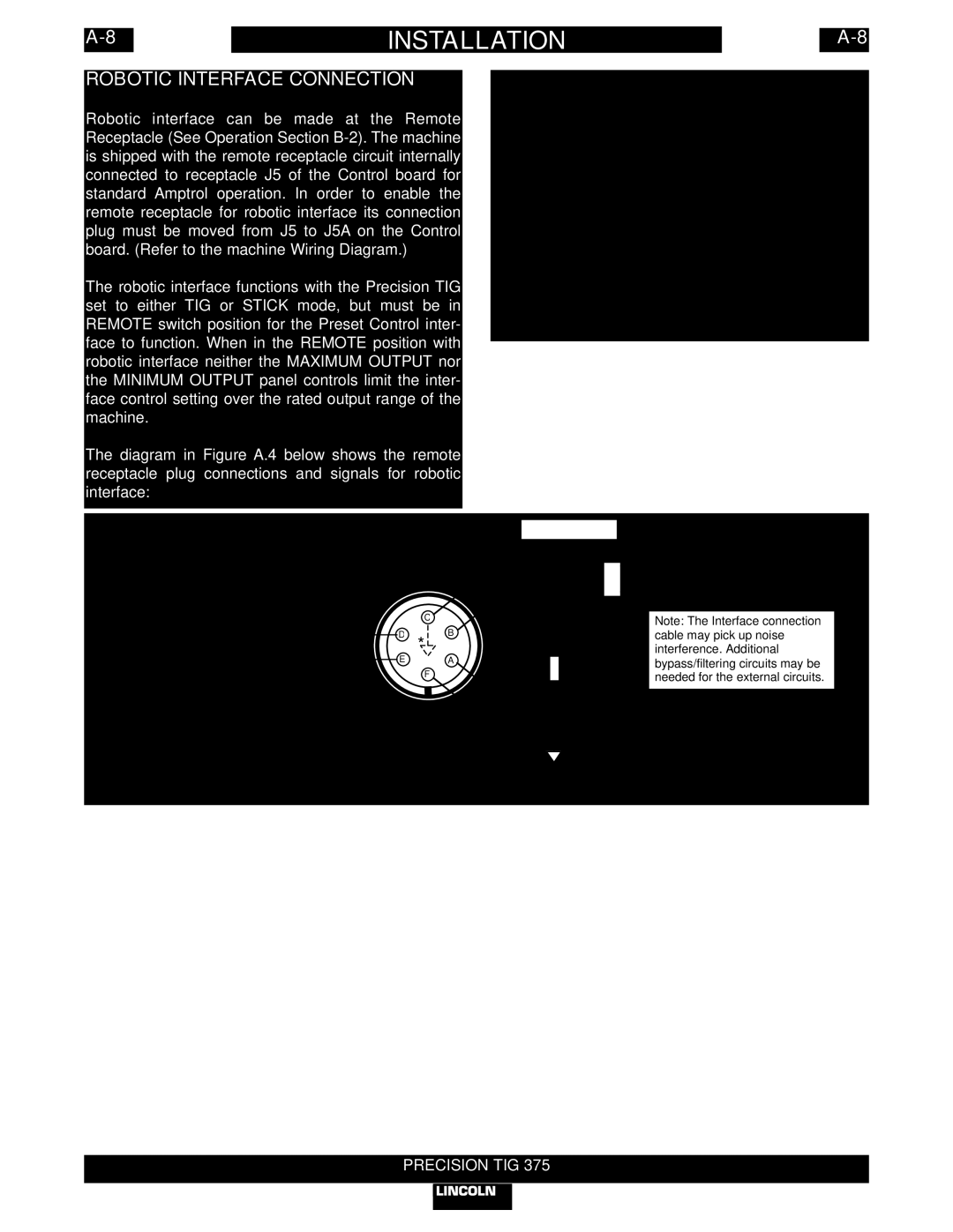
ROBOTIC INTERFACE CONNECTION
Robotic interface can be made at the Remote Receptacle (See Operation Section
The robotic interface functions with the Precision TIG set to either TIG or STICK mode, but must be in REMOTE switch position for the Preset Control inter- face to function. When in the REMOTE position with robotic interface neither the MAXIMUM OUTPUT nor the MINIMUM OUTPUT panel controls limit the inter- face control setting over the rated output range of the machine.
The diagram in Figure A.4 below shows the remote receptacle plug connections and signals for robotic interface:
REMOTE RECEPTACLE | FIGURE A.4 |
|
(Front View) |
| |
|
| |
For |
|
|
(LECO |
| PRESET CONTROL |
|
| |
| + | INPUT FROM ROBOT |
(0
ARC START
INPUT FROM ROBOT (18Vac,10ma switch)
| C | +VCC = 70Vdc max. | |
D | B | ||
| |||
* |
| ||
E | A | R = VCC / 5ma | |
| F | ||
|
| ||
|
| 5ma | |
* Precision TIG Control Common. | Robotic | ||
Common | |||
Note: The Interface connection cable may pick up noise interference. Additional bypass/filtering circuits may be needed for the external circuits.
ARC ESTABLISHED
OUTPUT TO ROBOT
(High = Not Welding)
(Low = Welding)