| LEARNING TO WELD |
| ||
|
|
|
|
|
FIGURE B.18
WARNING
ARC RAYS can burn eyes and skin.
When using an open arc process, it Is necessary to use correct eye, head and body protection.
Protect yourself and others, read “ARC RAYS can burn” at the front of this manual.
2.The Correct Way To Strike An Arc
1.Be sure the work clamp makes good electrical contact to the work.
2.Position gun over joint. End of wire may be lightly touching the work.
3.Position face shield to protect face and eyes, close gun trigger, and begin welding. Hold the gun so that the contact tip to work distance is about 3/8 to 1/2 inch (10 – 12 mm).
4.To stop welding, release the gun trigger and the pull the gun away from the work after the arc goes out.
5.A ball may form at the tip end of the wire after welding. For easier restrikes (with Innershield wire) the ball may be removed by feeding out a few inches of wire and simply bending the wire back and forth until it breaks off.
6.When no more welding is to be done, turn off the machine.
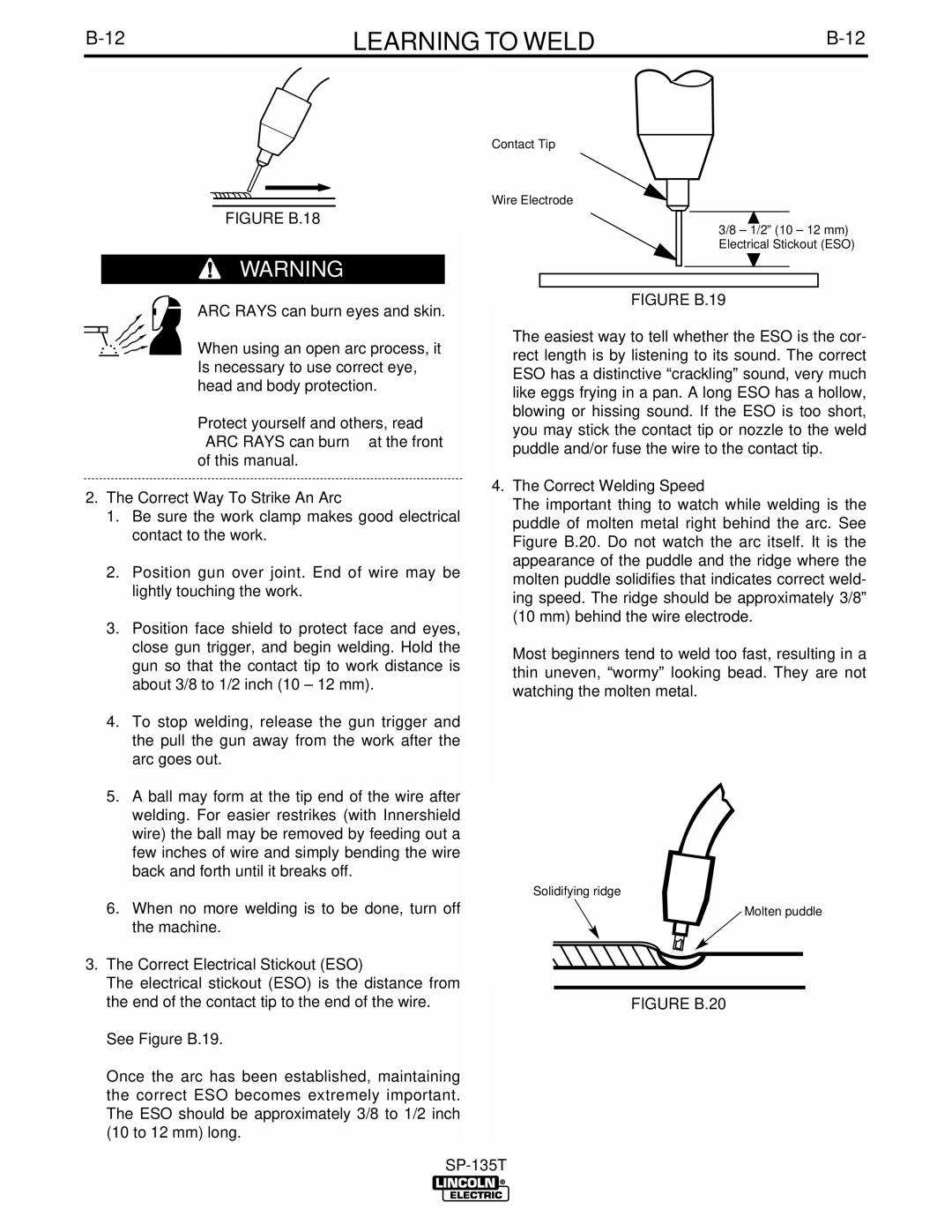
3.The Correct Electrical Stickout (ESO)
The electrical stickout (ESO) is the distance from the end of the contact tip to the end of the wire.
See Figure B.19.
Once the arc has been established, maintaining the correct ESO becomes extremely important. The ESO should be approximately 3/8 to 1/2 inch (10 to 12 mm) long.
Contact Tip
Wire Electrode
3/8 – 1/2” (10 – 12 mm) Electrical Stickout (ESO)
FIGURE B.19
The easiest way to tell whether the ESO is the cor- rect length is by listening to its sound. The correct ESO has a distinctive “crackling” sound, very much like eggs frying in a pan. A long ESO has a hollow, blowing or hissing sound. If the ESO is too short, you may stick the contact tip or nozzle to the weld puddle and/or fuse the wire to the contact tip.
4.The Correct Welding Speed
The important thing to watch while welding is the puddle of molten metal right behind the arc. See Figure B.20. Do not watch the arc itself. It is the appearance of the puddle and the ridge where the molten puddle solidifies that indicates correct weld- ing speed. The ridge should be approximately 3/8” (10 mm) behind the wire electrode.
Most beginners tend to weld too fast, resulting in a thin uneven, “wormy” looking bead. They are not watching the molten metal.
Solidifying ridge
Molten puddle