B-4 OPERATIONB-4
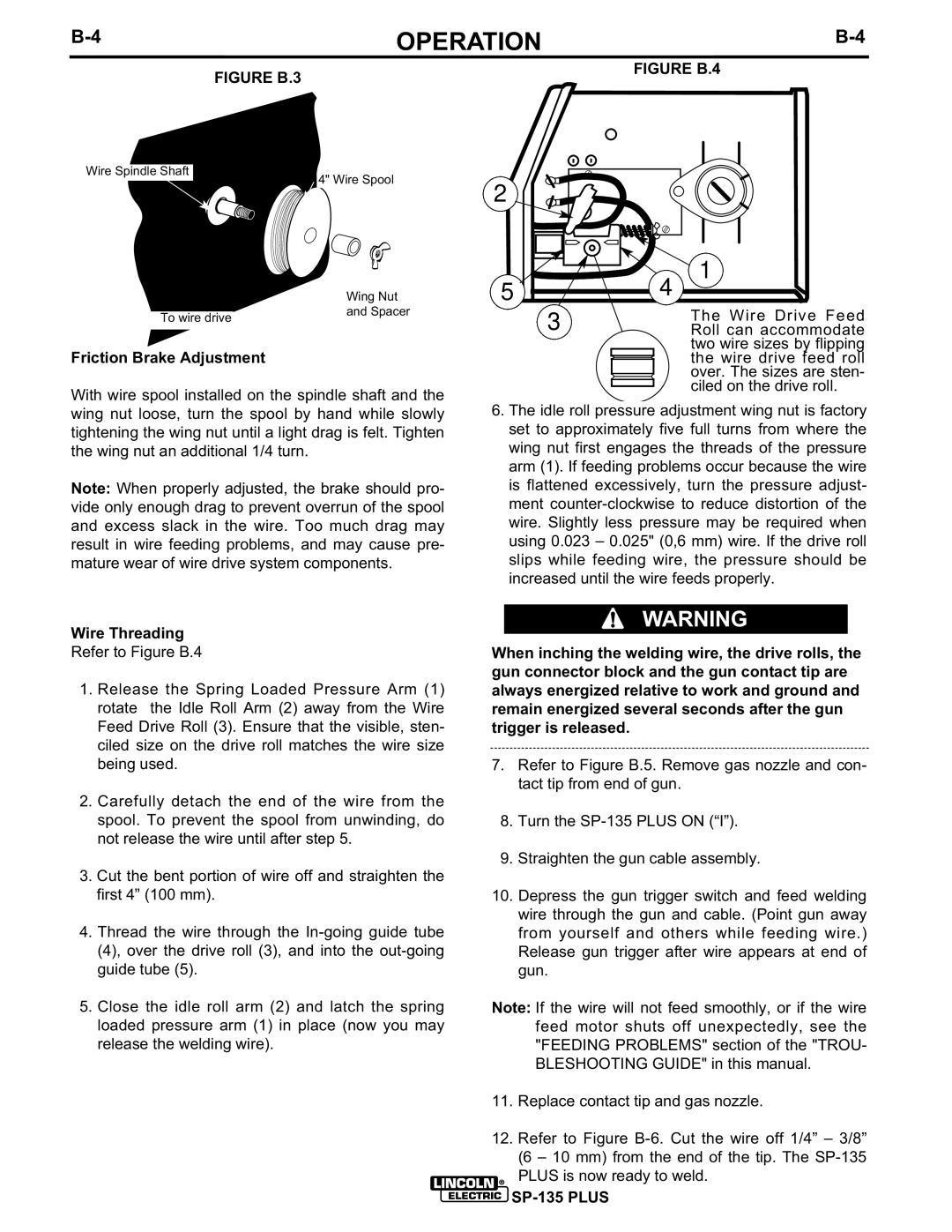
FIGURE B.3 | FIGURE B.4 |
|
Wire Spindle Shaft
4" Wire Spool
| Wing Nut |
To wire drive | and Spacer |
|
Friction Brake Adjustment
With wire spool installed on the spindle shaft and the wing nut loose, turn the spool by hand while slowly tightening the wing nut until a light drag is felt. Tighten the wing nut an additional 1/4 turn.
Note: When properly adjusted, the brake should pro- vide only enough drag to prevent overrun of the spool and excess slack in the wire. Too much drag may result in wire feeding problems, and may cause pre- mature wear of wire drive system components.
2
5 | 1 |
4 | |
3 | The Wire Drive Feed |
Roll can accommodate | |
| two wire sizes by flipping |
| the wire drive feed roll |
| over. The sizes are sten- |
| ciled on the drive roll. |
6.The idle roll pressure adjustment wing nut is factory set to approximately five full turns from where the wing nut first engages the threads of the pressure arm (1). If feeding problems occur because the wire is flattened excessively, turn the pressure adjust- ment
Wire Threading |
|
| WARNING |
| |
|
|
|
| ||
Refer to Figure B.4 | When inching the welding wire, the drive rolls, the | ||||
1. Release the Spring Loaded Pressure Arm (1) | gun connector block and the gun contact tip are | ||||
always energized relative to work and ground and | |||||
rotate the Idle Roll Arm (2) away from the Wire | remain energized several seconds after the gun | ||||
Feed Drive Roll (3). Ensure that the visible, sten- | trigger is released. | ||||
ciled size on the drive roll matches the wire size |
|
|
|
| |
being used. | 7. | Refer to Figure B.5. Remove gas nozzle and con- | |||
2. Carefully detach the end of the wire from the |
|
| tact tip from end of gun. | ||
|
|
|
| ||
spool. To prevent the spool from unwinding, do | 8. | Turn the | |||
not release the wire until after step 5. | 9. | Straighten the gun cable assembly. | |||
3. Cut the bent portion of wire off and straighten the | |||||
|
|
|
| ||
first 4” (100 mm). | 10. Depress the gun trigger switch and feed welding | ||||
4. Thread the wire through the |
|
| wire through the gun and cable. (Point gun away | ||
|
| from yourself and others while feeding wire.) | |||
(4), over the drive roll (3), and into the |
|
| Release gun trigger after wire appears at end of | ||
guide tube (5). |
|
| gun. | ||
5. Close the idle roll arm (2) and latch the spring | Note: If the wire will not feed smoothly, or if the wire | ||||
loaded pressure arm (1) in place (now you may |
|
| feed motor shuts off unexpectedly, see the | ||
release the welding wire). |
|
| "FEEDING PROBLEMS" section of the "TROU- | ||
|
|
| BLESHOOTING GUIDE" in this manual. | ||
| 11. | Replace contact tip and gas nozzle. | |||
| 12. | Refer to Figure | |||
|
|
| (6 – 10 mm) from the end of the tip. The | ||
|
|
| PLUS is now ready to weld. | ||