INSTALLATION | ||
|
|
|
POWER SOURCE TO LN25 PRO EXTREME
CABLE CONNECTION DIAGRAMS
ACROSS THE ARC SET-UPS
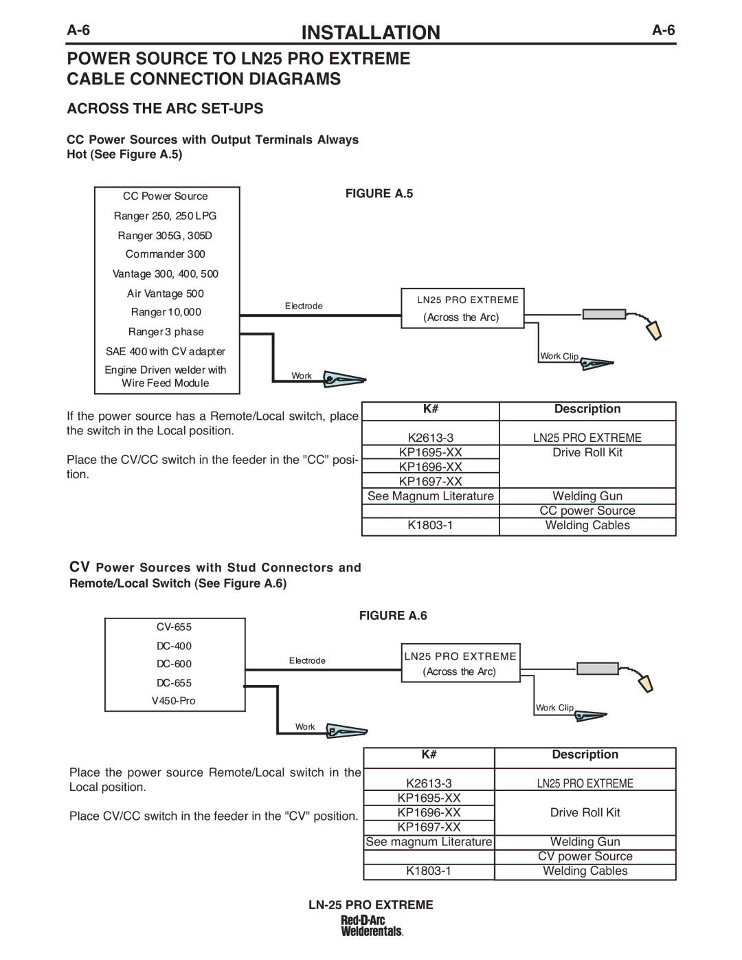
CCPower Sources with Output Terminals Always Hot (See Figure A.5)
FIGURE A.5
If the power source has a Remote/Local switch, place the switch in the Local position.
Place the CV/CC switch in the feeder in the "CC" posi- tion.
CV Power Sources with Stud Connectors and Remote/Local Switch (See Figure A.6)
K# | Description |
|
|
LN25 PRO EXTREME | |
Drive Roll Kit | |
| |
| |
See Magnum Literature | Welding Gun |
| CC power Source |
Welding Cables | |
|
|
FIGURE A.6
Place the power source Remote/Local switch in the Local position.
Place CV/CC switch in the feeder in the "CV" position.
K# | Description |
|
|
LN25 PRO EXTREME | |
| |
Drive Roll Kit | |
| |
See magnum Literature | Welding Gun |
| CV power Source |
Welding Cables |