Manuals
/
Lincoln Electric
/
Power Tools
/
Welder
Lincoln Electric
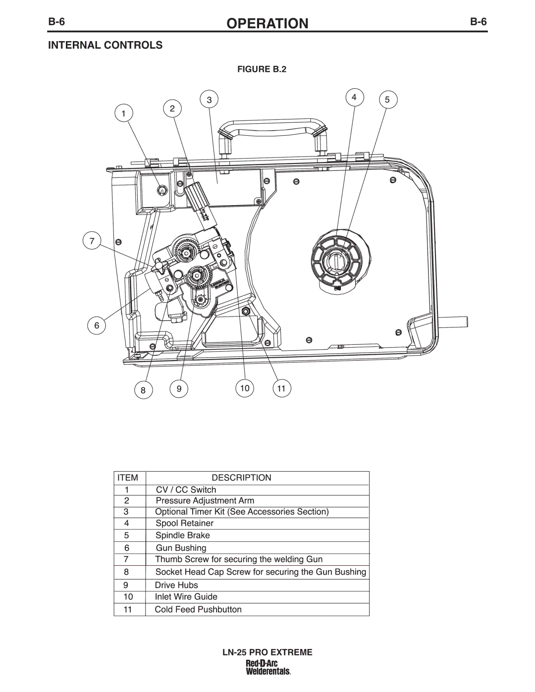
IM-939A, 11523, 11389 Internal Controls, Figure B.2 LN-25 PRO Extreme
Models:
11389
11523
IM-939A
LN-25
1
21
42
42
Download
42 pages
49.5 Kb
18
19
20
21
22
23
24
25
Troubleshooting
Specification
Install
Diagrams
Wire Drive Configuration
Dimension
Output Problems
Accessories
Pressure ARM Adjustment
Safety Precautions
Page 21
Image 21
B-6
OPERATION
B-6
INTERNAL CONTROLS
FIGURE B.2
LN-25
PRO EXTREME
Page 20
Page 22
Page 21
Image 21
Page 20
Page 22
Contents
LN-25 PRO Extreme
LN-25 PRO Extreme
Safety
Electric Shock can kill
Cylinder may explode if damaged
Sûreté Pour Soudage a LʼArc
Précautions DE Sûreté
Thank You
Table of Contents
Technical Specifications LN25 PRO K2613-3
Installation
Location
Safety Precautions
High Frequency Protection
Weld Cable Size
Cable Connections
Shielding GAS Connection
Build UP of Shielding GAS MAY Harm Health or Kill
Wire Drive Configuration
Procedure to Install Drive Rolls and Wire Guides
Changing the GUN Receiver Bushing
Pressure ARM Adjustment
Loading Spools of Wire
GUN Connection
Across the ARC SET-UPS
Power Source to LN25 PRO Extreme Cable Connection Diagrams
Figure A.7
Figure A.9
Operation
Safety Precautions
General Description
Analog Voltmeter
Figure B.1 Description
Wire Feed Speed, CV Operation
Wire Feed Speed Knob
Polarity LED
Figure B.2 LN-25 PRO Extreme
Internal Controls
Cold Feed Pushbutton
CV/CC Switch
Figure B-3
Constant Current Wire Welding
Rear Controls GAS Purge Pushbutton
POWER-UP Sequence
Factory Installed Equipment
Accessories
Wire Type Electrode Size KP KIT
Drive Roll Kits
Accessories
Accessories
K1500-5 Gun Receiver Bushing compatible
Routine Maintenance
Maintenance
Periodic Maintenance
Calibration Specification
Board LN-25 PRO Extreme
Cover
HOW to USE Troubleshooting Guide
Troubleshooting
Digital Display Models Error Codes
Output Problems
Troubleshooting
Diagrams
Diagrams
Dimension Print
LN-25 PRO Extreme
LN-25 PRO Extreme
Precaucion
Warnung
Top
Page
Image
Contents