INSTALLATION | ||
|
|
|
INPUT CONNECTIONS
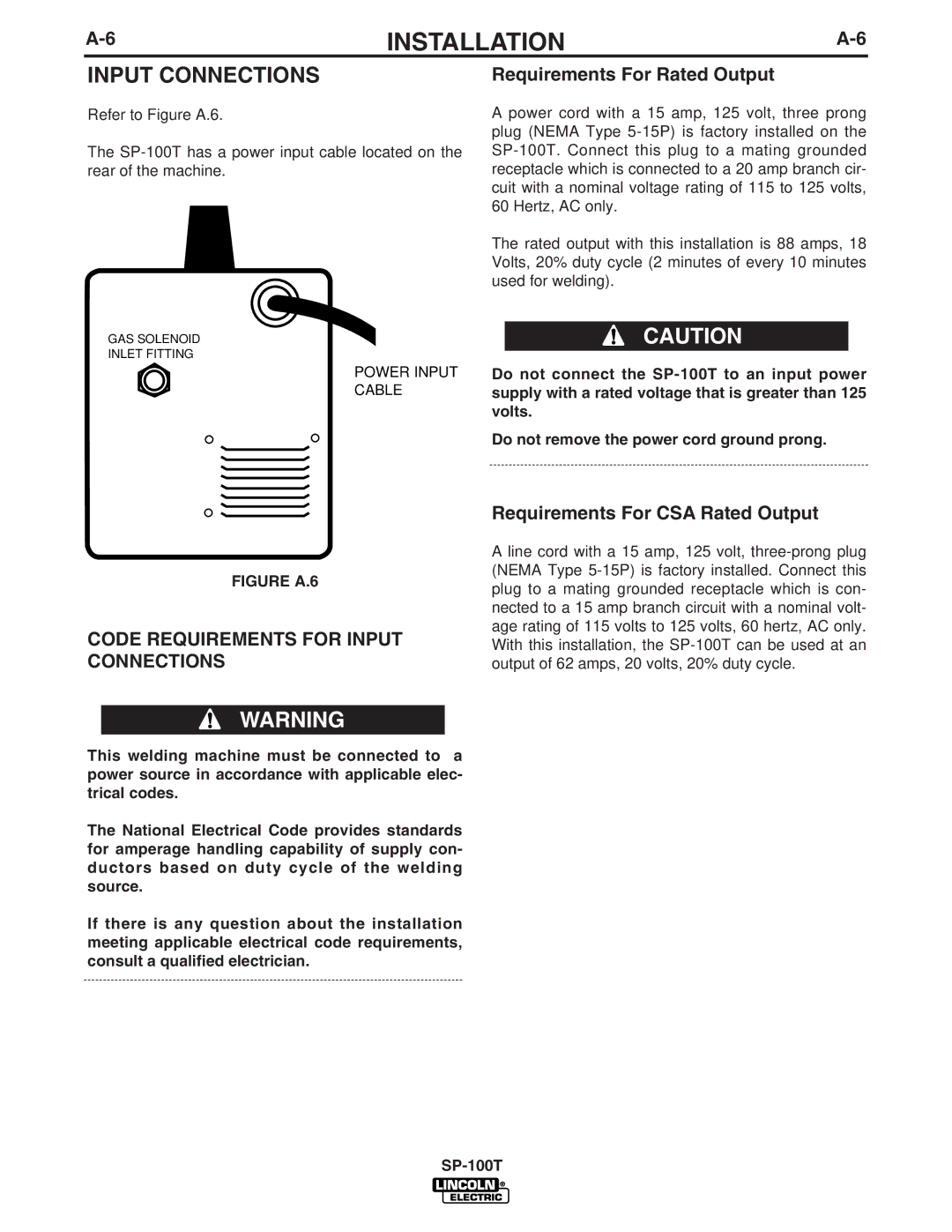
Refer to Figure A.6.
The
GAS SOLENOID
INLET FITTING
POWER INPUT
CABLE
Requirements For Rated Output
A power cord with a 15 amp, 125 volt, three prong plug (NEMA Type
The rated output with this installation is 88 amps, 18 Volts, 20% duty cycle (2 minutes of every 10 minutes used for welding).
CAUTION
Do not connect the
Do not remove the power cord ground prong.
FIGURE A.6
CODE REQUIREMENTS FOR INPUT CONNECTIONS
WARNING
This welding machine must be connected to a power source in accordance with applicable elec- trical codes.
The National Electrical Code provides standards for amperage handling capability of supply con- ductors based on duty cycle of the welding source.
If there is any question about the installation meeting applicable electrical code requirements, consult a qualified electrician.
Requirements For CSA Rated Output
A line cord with a 15 amp, 125 volt,