XD-V75 specifications
The Line 6 XD-V75 is a professional digital wireless microphone system that has made a significant impact in live sound environments, including concerts, theater productions, and public speaking engagements. This system is designed to provide superior sound quality and exceptional performance, aiming to meet the demands of both professional musicians and vocalists.One of the standout features of the XD-V75 is its advanced digital transmission technology. The system operates in the 2.4 GHz frequency band, which is licensed-free and allows for interference-free operation, minimizing the risk of dropouts and RF interference. This ensures that performers can move freely on stage without compromising audio quality.
The XD-V75 comes equipped with high-fidelity, 24-bit digital audio, delivering pristine sound quality that remains consistent across various volume levels. This high resolution provides a remarkable dynamic range, making it suitable for capturing both soft spoken lines and powerful vocals. The built-in microphone options, including cardioid and omnidirectional polarization, further enhance versatility, catering to different performance environments and stylistic preferences.
This system also features up to 12 channels of operation, allowing multiple users to perform simultaneously without interference. Channel scanning technology helps quickly identify and select the best available channels, streamlining setup time and ensuring reliable performance.
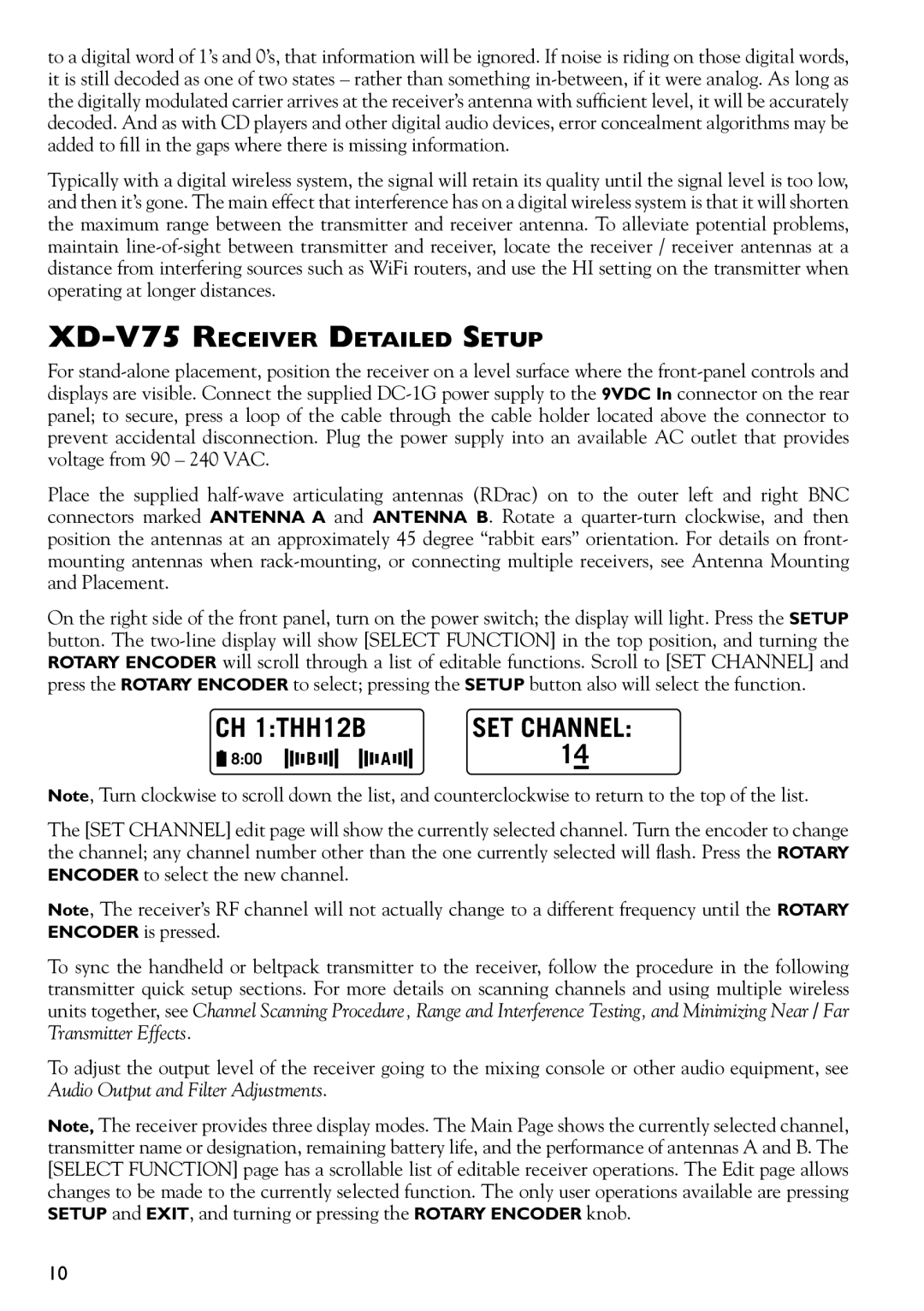
Another noteworthy aspect of the XD-V75 is its user-friendly interface. The system includes an LCD screen that provides clear visual feedback regarding battery life, signal strength, and channel selection. This allows users to monitor their setup at a glance and make real-time adjustments during performances.
Durability is also a central characteristic of the Line 6 XD-V75. The transmitter and receiver units are built to withstand the rigors of daily use, from touring musicians to corporate events. The handheld transmitters are ergonomically designed for comfort and ease of use, while the bodypack transmitters allow for versatility in placement, accommodating instruments and lavalier microphones.
With its combination of professional-grade audio quality, robust wireless performance, and versatile design, the Line 6 XD-V75 continues to be a preferred choice for performers around the world who demand the best from their wireless microphone systems. This enables artists and speakers to focus on their performance, knowing they have a reliable and high-quality audio solution in the Line 6 XD-V75.
