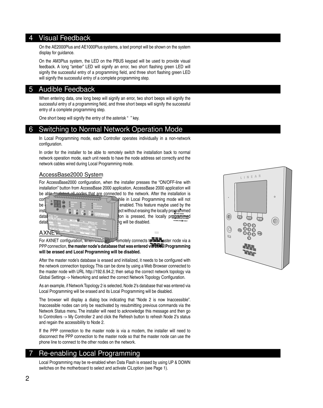
AM3Plus, AE2000Plus, AE1000Plus specifications
The Linear AE1000Plus is a sophisticated access control and security system designed to meet the unique needs of residential and commercial environments. This advanced model is part of Linear’s commitment to providing reliable and efficient security solutions. It offers enhanced features, cutting-edge technologies, and exceptional characteristics that set it apart in the market.One of the standout features of the AE1000Plus is its versatility in handling various access control modes. It supports access via key fobs, keypads, and biometric scanners, allowing for seamless integration with existing systems. This flexibility ensures that users can select the most appropriate method for their security requirements, enhancing convenience without compromising safety.
The AE1000Plus incorporates advanced wireless technology that facilitates easier installation and use. This wireless capability eliminates the need for extensive wiring, significantly reducing installation time and costs. Additionally, the system can communicate with Linear's extensive range of peripherals, including security cameras and alarm systems, providing a comprehensive security solution.
Another notable characteristic is its robust capacity for managing multiple users. The AE1000Plus can store a substantial number of user codes and fobs, making it ideal for larger facilities or properties with frequent visitor access. This feature empowers administrators with control over who can access specific areas while maintaining an audit trail of entries and exits.
The system is built with a user-friendly interface, ensuring ease of operation for both administrators and users. Programming and configuration can be streamlined through intuitive menus, while easily accessible manuals provide guidance for troubleshooting and adjustments. User experience is further enhanced by the AE1000Plus's compatibility with mobile applications, able to manage access remotely.
Security is paramount, and the AE1000Plus excels in implementing high-security standards. It employs encryption protocols that protect transmitted data from unauthorized access, ensuring the integrity and confidentiality of user information. The system is also designed to perform reliably in various environmental conditions, making it suitable for outdoor applications.
In summary, the Linear AE1000Plus combines versatility, advanced technology, and user-oriented design to create a leading access control solution. Its array of features ensures robust security while offering the flexibility to meet the demands of various settings, confirming Linear's position as a trusted name in the security industry. Whether for residential or commercial use, the AE1000Plus stands out as a reliable choice for modern security needs.

