Basic Controller Programming


Programming Overview


PROGRAM


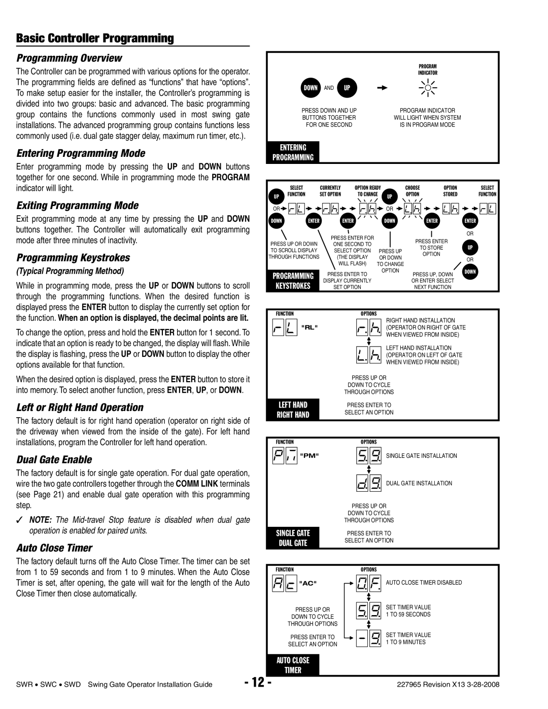
The Controller can be programmed with various options for the operator.


INDICATOR


The programming fi elds are defi ned as “functions” that have “options”.


DOWN


AND


UP


To make setup easier for the installer, the Controller’s programming is


divided into two groups: basic and advanced. The basic programming


PRESS DOWN AND UP


PROGRAM INDICATOR


group contains the functions commonly used in most swing gate


BUTTONS TOGETHER


WILL LIGHT WHEN SYSTEM


installations. The advanced programming group contains functions less


FOR ONE SECOND


IS IN PROGRAM MODE


commonly used (i.e. dual gate stagger delay, maximum run timer, etc.).


Entering Programming Mode


ENTERING


PROGRAMMING


Enter programming mode by pressing the UP and DOWN buttons


together for one second. While in programming mode the PROGRAM


indicator will light.


SELECT

CURRENTLY


OPTION READY


CHOOSE


OPTION


SELECT


UP


FUNCTION

SET OPTION


TO CHANGE


UP

OPTION


STORED

FUNCTION

Exiting Programming Mode


OR


OR


Exit programming mode at any time by pressing the UP and DOWN


DOWN


ENTER


ENTER


DOWN


ENTER

ENTER

buttons together. The Controller will automatically exit programming


PRESS ENTER FOR


OR


mode after three minutes of inactivity.


PRESS UP OR DOWN


PRESS ENTER


ONE SECOND TO


UP


TO SCROLL DISPLAY


SELECT OPTION

PRESS UP


TO STORE

Programming Keystrokes


OPTION


THROUGH FUNCTIONS


(THE DISPLAY

OR DOWN


OR


(Typical Programming Method)


WILL FLASH) TO CHANGE


OPTION


DOWN


PROGRAMMING


PRESS ENTER TO


PRESS UP, DOWN


While in programming mode, press the UP or DOWN buttons to scroll


KEYSTROKES


DISPLAY CURRENTLY


OR ENTER SELECT


SET OPTION


NEXT FUNCTION


through the programming functions. When the desired function is


displayed press the ENTER button to display the currently set option for


the function. When an option is displayed, the decimal points are lit.


FUNCTION


OPTIONS


"RL"


RIGHT HAND INSTALLATION


To change the option, press and hold the ENTER button for 1 second. To


(OPERATOR ON RIGHT OF GATE


WHEN VIEWED FROM INSIDE)


indicate that an option is ready to be changed, the display will fl ash. While


LEFT HAND INSTALLATION


the display is fl ashing, press the UP or DOWN button to display the other


(OPERATOR ON LEFT OF GATE


options available for that function.


WHEN VIEWED FROM INSIDE)


When the desired option is displayed, press the ENTER button to store it


PRESS UP OR


into memory. To select another function, press ENTER, UP, or DOWN.


DOWN TO CYCLE


THROUGH OPTIONS


Left or Right Hand Operation


LEFT HAND


PRESS ENTER TO


The factory default is for right hand operation (operator on right side of


RIGHT HAND


SELECT AN OPTION


the driveway when viewed from the inside of the gate). For left hand


installations, program the Controller for left hand operation.


FUNCTION


OPTIONS


Dual Gate Enable


"PM"


SINGLE GATE INSTALLATION


The factory default is for single gate operation. For dual gate operation,


wire the two gate controllers together through the COMM LINK terminals


DUAL GATE INSTALLATION


(see Page 21) and enable dual gate operation with this programming


step.


PRESS UP OR


NOTE: The Mid-travel Stop feature is disabled when

dual gate


DOWN TO CYCLE


THROUGH OPTIONS


operation is enabled for paired units.


SINGLE GATE


PRESS ENTER TO


Auto Close Timer


DUAL GATE


SELECT AN OPTION


The factory default turns off the Auto Close Timer. The timer can be set


from 1 to 59 seconds and from 1 to 9 minutes. When the Auto Close


FUNCTION


OPTIONS


Timer is set, after opening, the gate will wait for the length of the Auto


"AC"


AUTO CLOSE TIMER DISABLED


Close Timer then close automatically.


SET TIMER VALUE


PRESS UP OR


1 TO 59 SECONDS


DOWN TO CYCLE


THROUGH OPTIONS


SET TIMER VALUE


PRESS ENTER TO


1 TO 9 MINUTES


SELECT AN OPTION


AUTO CLOSE


- 12


TIMER


SWR SWC SWD Swing Gate Operator Installation Guide

-


227965 Revision X13 3-28-2008

Page 14
Image 14
Linear SWC, SWR, SWD manual Basic Controller Programming

SWR, SWD, SWC specifications

Linear SWC (Single Wire Control), SWD (Single Wire Debug), and SWR (Single Wire Radio) are advanced communication protocols widely utilized in embedded systems and electronic applications. These protocols enhance the efficiency of data transmission, reduce the number of physical connections required, and simplify the design process for developers.

The main feature of Linear SWC is its ability to transmit control signals over a single wire, allowing for straightforward connectivity between microcontrollers and various peripherals. This approach minimizes the complexity of printed circuit boards (PCBs) and reduces the space needed for connections, making it ideal for compact designs. Linear SWC operates based on a master/slave architecture, where the master device initiates communication, and the slave devices respond.

SWD, primarily used for debugging embedded systems, is a two-pin interface that supports high-speed data transfer with minimal pin usage. Unlike traditional JTAG, SWD is simpler and more efficient, allowing developers to perform debugging and programming tasks with fewer resources. The SWD protocol offers features such as breakpoint management, memory read/write capabilities, and real-time variable monitoring, empowering developers to optimize their code and increase debugging efficiency.

SWR is focused on wireless communication, leveraging a single wire for transmitting radio signals. This technology is particularly advantageous in applications requiring minimal hardware while maintaining robust connectivity. SWR supports various modulation techniques and can operate in different frequency bands, making it versatile for various use cases. The single-wire approach reduces the complexity of antenna design and enhances the overall reliability of wireless communications in challenging environments.

One of the key characteristics shared by SWC, SWD, and SWR is their ability to reduce power consumption. By minimizing the number of connections and optimizing signal paths, these protocols significantly decrease the energy required for data transmission. Additionally, their compatibility with a wide range of microcontrollers and integrated circuits contributes to their widespread adoption in modern electronic designs.

In summary, Linear SWC, SWD, and SWR serve critical roles in the evolution of embedded systems, offering unique features, advanced technologies, and efficient characteristics. Their capability to simplify designs, reduce power consumption, and enhance overall communication quality makes them essential tools for engineers and developers in today's fast-paced technological landscape. As the demand for compact, efficient solutions grows, these protocols are poised to play an increasingly significant role in future innovations.