Operator Setup

Controller Access

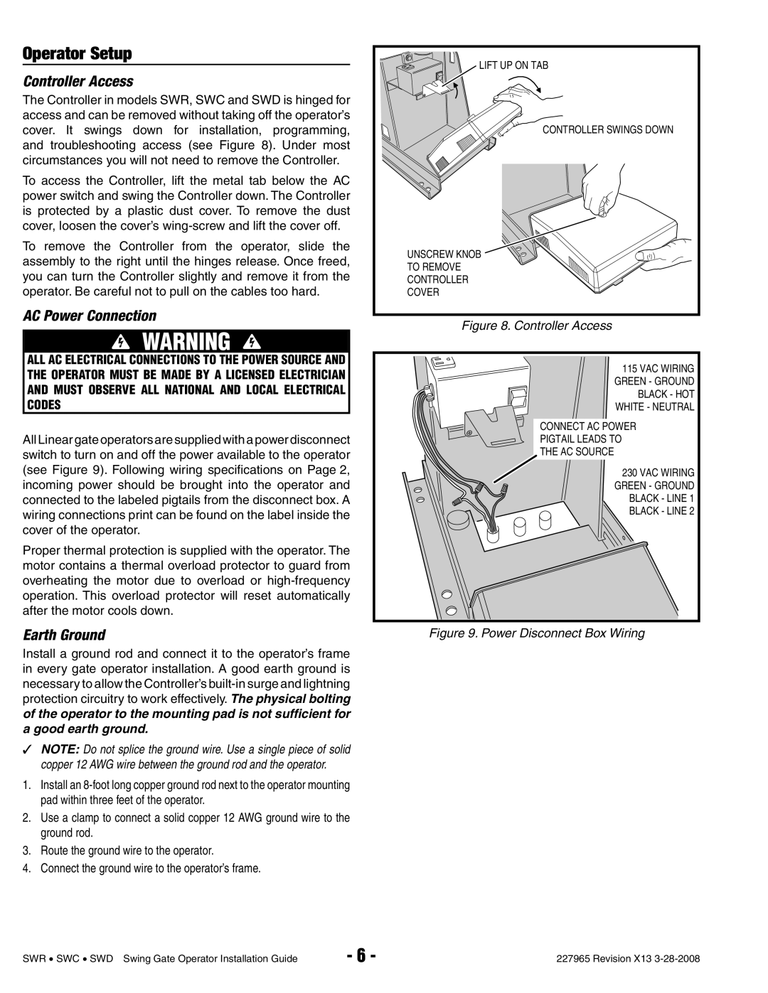
The Controller in models SWR, SWC and SWD is hinged for access and can be removed without taking off the operator’s cover. It swings down for installation, programming, and troubleshooting access (see Figure 8). Under most circumstances you will not need to remove the Controller.

To access the Controller, lift the metal tab below the AC power switch and swing the Controller down. The Controller is protected by a plastic dust cover. To remove the dust cover, loosen the cover’s wing-screw and lift the cover off.

To remove the Controller from the operator, slide the assembly to the right until the hinges release. Once freed, you can turn the Controller slightly and remove it from the operator. Be careful not to pull on the cables too hard.

AC Power Connection

WARNING

ALL AC ELECTRICAL CONNECTIONS TO THE POWER SOURCE AND THE OPERATOR MUST BE MADE BY A LICENSED ELECTRICIAN AND MUST OBSERVE ALL NATIONAL AND LOCAL ELECTRICAL CODES

All Linear gate operators are supplied with a power disconnect switch to turn on and off the power available to the operator (see Figure 9). Following wiring specifi cations on Page 2, incoming power should be brought into the operator and connected to the labeled pigtails from the disconnect box. A wiring connections print can be found on the label inside the cover of the operator.

Proper thermal protection is supplied with the operator. The motor contains a thermal overload protector to guard from overheating the motor due to overload or high-frequency operation. This overload protector will reset automatically after the motor cools down.

Earth Ground

Install a ground rod and connect it to the operator’s frame in every gate operator installation. A good earth ground is necessary to allow the Controller’s built-in surge and lightning protection circuitry to work effectively. The physical bolting of the operator to the mounting pad is not sufficient for a good earth ground.

NOTE: Do not splice the ground wire. Use a single piece of solid copper 12 AWG wire between the ground rod and the operator.

1.Install an 8-foot long copper ground rod next to the operator mounting pad within three feet of the operator.

2.Use a clamp to connect a solid copper 12 AWG ground wire to the ground rod.

3.Route the ground wire to the operator.

4.Connect the ground wire to the operator’s frame.

LIFT UP ON TAB

CONTROLLER SWINGS DOWN

UNSCREW KNOB

TO REMOVE

CONTROLLER

COVER

Figure 8. Controller Access

115 VAC WIRING GREEN - GROUND BLACK - HOT WHITE - NEUTRAL

CONNECT AC POWER

PIGTAIL LEADS TO

THE AC SOURCE

230 VAC WIRING GREEN - GROUND BLACK - LINE 1 BLACK - LINE 2

Figure 9. Power Disconnect Box Wiring

SWR SWC SWD Swing Gate Operator Installation Guide

- 6 -

227965 Revision X13 3-28-2008

Page 8
Image 8
Linear SWC, SWR, SWD manual Operator Setup, Controller Access, AC Power Connection, Earth Ground

SWR, SWD, SWC specifications

Linear SWC (Single Wire Control), SWD (Single Wire Debug), and SWR (Single Wire Radio) are advanced communication protocols widely utilized in embedded systems and electronic applications. These protocols enhance the efficiency of data transmission, reduce the number of physical connections required, and simplify the design process for developers.

The main feature of Linear SWC is its ability to transmit control signals over a single wire, allowing for straightforward connectivity between microcontrollers and various peripherals. This approach minimizes the complexity of printed circuit boards (PCBs) and reduces the space needed for connections, making it ideal for compact designs. Linear SWC operates based on a master/slave architecture, where the master device initiates communication, and the slave devices respond.

SWD, primarily used for debugging embedded systems, is a two-pin interface that supports high-speed data transfer with minimal pin usage. Unlike traditional JTAG, SWD is simpler and more efficient, allowing developers to perform debugging and programming tasks with fewer resources. The SWD protocol offers features such as breakpoint management, memory read/write capabilities, and real-time variable monitoring, empowering developers to optimize their code and increase debugging efficiency.

SWR is focused on wireless communication, leveraging a single wire for transmitting radio signals. This technology is particularly advantageous in applications requiring minimal hardware while maintaining robust connectivity. SWR supports various modulation techniques and can operate in different frequency bands, making it versatile for various use cases. The single-wire approach reduces the complexity of antenna design and enhances the overall reliability of wireless communications in challenging environments.

One of the key characteristics shared by SWC, SWD, and SWR is their ability to reduce power consumption. By minimizing the number of connections and optimizing signal paths, these protocols significantly decrease the energy required for data transmission. Additionally, their compatibility with a wide range of microcontrollers and integrated circuits contributes to their widespread adoption in modern electronic designs.

In summary, Linear SWC, SWD, and SWR serve critical roles in the evolution of embedded systems, offering unique features, advanced technologies, and efficient characteristics. Their capability to simplify designs, reduce power consumption, and enhance overall communication quality makes them essential tools for engineers and developers in today's fast-paced technological landscape. As the demand for compact, efficient solutions grows, these protocols are poised to play an increasingly significant role in future innovations.