Using Features and Options
Table 6-1. Optional Monitoring Accessories
Number and Type of Accessories Permitted
Remote Monitor Panel | Relay Interface Module | Supervisory Contact Module |
|
|
|
2 | — | — |
|
|
|
— | 2 | — |
|
|
|
— | — | 2 |
|
|
|
1 | 1 | — |
|
|
|
1 | — | 1 |
|
|
|
— | 1 | 1 |
|
|
|
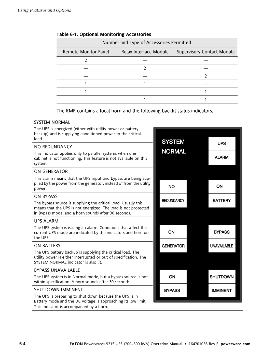
The RMP contains a local horn and the following backlit status indicators:
SYSTEM NORMAL
The UPS is energized (either with utility power or battery backup) and is supplying conditioned power to the critical load.
NO REDUNDANCY
This indicator applies only to parallel systems when one cabinet is not functioning. This feature is not available on this system.
ON GENERATOR
This alarm means that the UPS input and bypass are being sup- plied by the power from the generator, instead of from the utility power.
ON BYPASS
The bypass source is supplying the critical load. Usually this means that the UPS is not energized. The load is not protected in Bypass mode, and a horn sounds after 30 seconds.
UPS ALARM
The UPS system is issuing an alarm. Conditions that affect the current UPS mode are indicated by the indicators and horn on the UPS.
ON BATTERY
The UPS battery backup is supplying the critical load. The utility power is either interrupted or out of specification. The SYSTEM NORMAL indicator is also lit.
BYPASS UNAVAILABLE
The UPS system is in Normal mode, but a bypass source is not within specification. A horn sounds after 30 seconds.
SHUTDOWN IMMINENT
The UPS is preparing to shut down because the UPS is in
Battery mode and the DC voltage is approaching its low limit.
This indicator is accompanied by a horn.
EATON Powerware® 9315 UPS |