Using the Monitor Panel
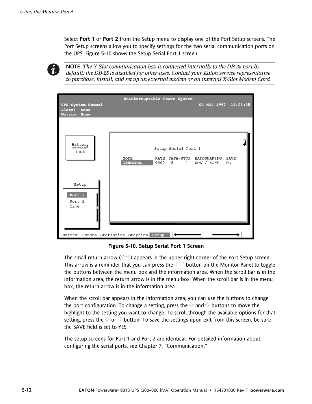
Select Port 1 or Port 2 from the Setup menu to display one of the Port Setup screens. The Port Setup screens allow you to specify settings for the two serial communication ports on the UPS. Figure
NOTE The
|
| Uninterruptible Power System |
|
| |||
UPS System Normal |
|
|
| 04 NOV 1997 | 14:23:45 | ||
Alarm: | None |
|
|
|
|
|
|
Notice: None |
|
|
|
|
|
| |
Battery |
|
|
|
|
|
| |
Percent |
| Setup Serial Port 1 |
| ||||
100% |
|
|
|
|
|
| |
|
| MODE | RATE | DATA/STOP | HANDSHAKING | SAVE | |
|
| TERMINAL | 9600 | 8 | 1 | XON / XOFF | NO |
Setup |
|
|
|
|
|
| |
Port 1 |
|
|
|
|
|
| |
Port 2 |
|
|
|
|
|
| |
Time |
|
|
|
|
|
|
|
Meters | Events | Statistics Graphics | Setup |
|
|
|
|
Figure 5-10. Setup Serial Port 1 Screen
The small return arrow (![]() ) appears in the upper right corner of the Port Setup screen.
) appears in the upper right corner of the Port Setup screen.
This arrow is a reminder that you can press the ![]() button on the Monitor Panel to toggle the buttons between the menu box and the information area. When the scroll bar is in the information area, the return arrow is in the menu box. When the scroll bar is in the menu box, the return arrow is in the information area.
button on the Monitor Panel to toggle the buttons between the menu box and the information area. When the scroll bar is in the information area, the return arrow is in the menu box. When the scroll bar is in the menu box, the return arrow is in the information area.
When the scroll bar appears in the information area, you can use the buttons to change the port configuration. To change a setting, press the ![]() and
and ![]() buttons to move the highlight to the setting you want to change. To scroll through the available options for that setting, press the
buttons to move the highlight to the setting you want to change. To scroll through the available options for that setting, press the ![]() or
or ![]() button. To save the settings upon exit from this screen, be sure the SAVE field is set to YES.
button. To save the settings upon exit from this screen, be sure the SAVE field is set to YES.
The setup screens for Port 1 and Port 2 are identical. For detailed information about configuring the serial ports, see Chapter 7, “Communication.”
EATON Powerware® 9315 UPS |