Communication
+24V | 1 | 6 | NOT USED | |
2 | ||||
485+ | ||||
7 | ||||
3 | ||||
485– | ||||
8 | ||||
NOT USED | ||||
4 | ||||
RETURN | ||||
RETURN | 9 | |||
5 | ||||
| ||||
|
|
|
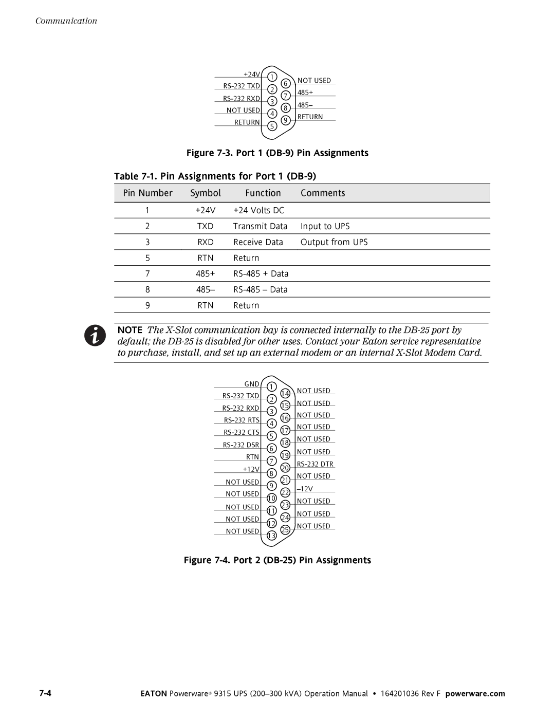
Figure 7-3. Port 1 (DB-9) Pin Assignments
Table 7-1. Pin Assignments for Port 1 (DB-9)
Pin Number | Symbol | Function | Comments | |
|
|
|
| |
1 | +24V | +24 Volts DC |
| |
|
|
|
| |
2 | TXD | Transmit Data | Input to UPS | |
|
|
|
| |
3 | RXD | Receive Data | Output from UPS | |
|
|
|
|
|
5 | RTN | Return |
|
|
|
|
|
|
|
7 | 485+ | + Data |
| |
|
|
|
|
|
8 | 485– | – Data |
| |
|
|
|
|
|
9 | RTN | Return |
|
|
|
|
|
|
|
NOTE The
GND | 1 | 14 | NOT USED | |
2 | ||||
NOT USED | ||||
15 | ||||
3 | ||||
16 | NOT USED | |||
4 | ||||
NOT USED | ||||
17 | ||||
5 | ||||
NOT USED | ||||
18 | ||||
6 | ||||
NOT USED | ||||
RTN | 19 | |||
7 | ||||
+12V | 20 | |||
8 | ||||
NOT USED | ||||
NOT USED | 21 | |||
9 | ||||
NOT USED | 22 | |||
10 | ||||
NOT USED | ||||
NOT USED | 23 | |||
| ||||
11 | NOT USED | |||
NOT USED | 24 | |||
12 | ||||
NOT USED | ||||
NOT USED | 25 | |||
13 |
| |||
|
|
|
Figure 7-4. Port 2 (DB-25) Pin Assignments
EATON Powerware® 9315 UPS |