800 SERIES
LINK ELECTRONICS, INC.
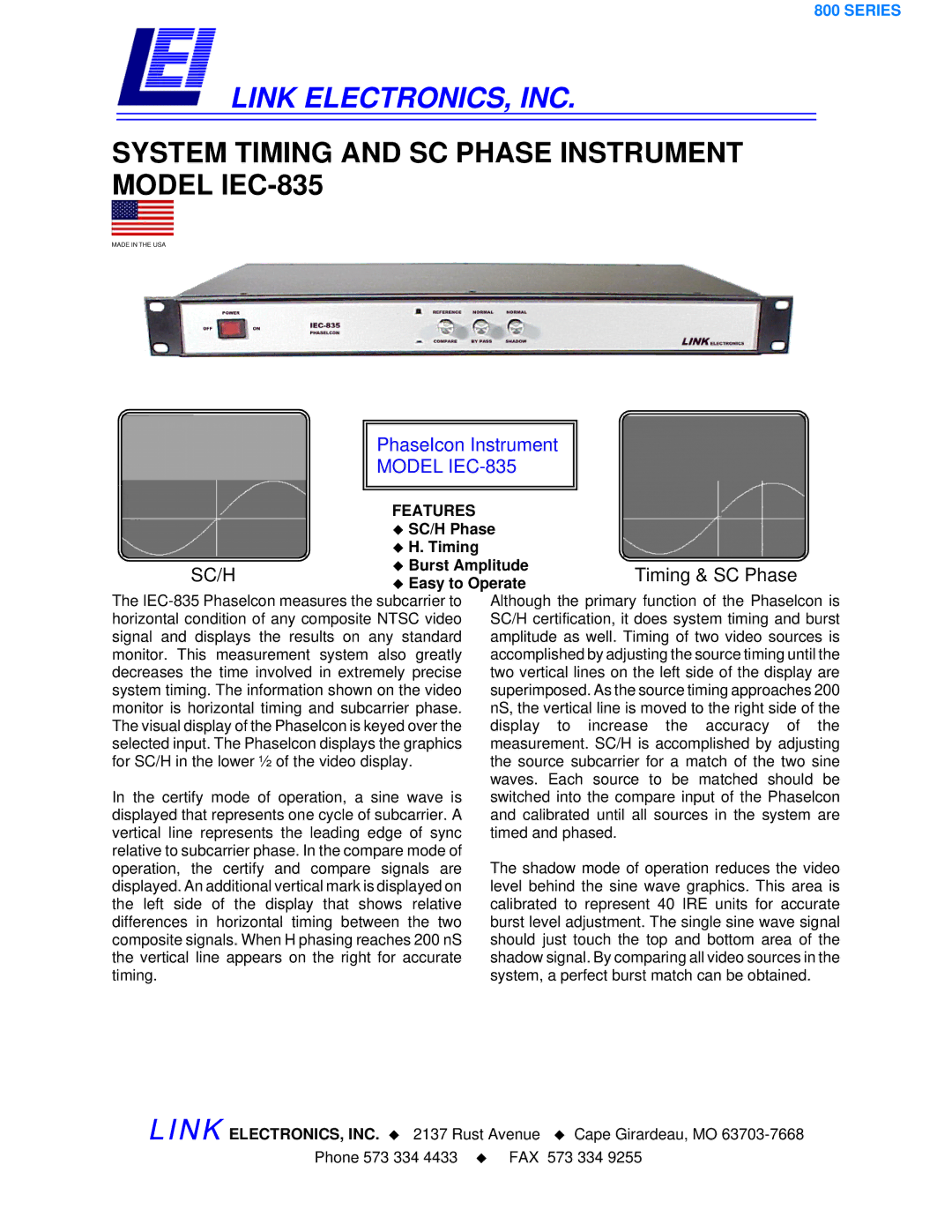
SYSTEM TIMING AND SC PHASE INSTRUMENT MODEL IEC-835
MADE IN THE USA
PhaseIcon Instrument
MODEL IEC-835
|
| FEATURES |
|
|
|
| SC/H Phase |
| |
|
| H. Timing |
|
|
|
|
|
| |
| SC/H | Burst Amplitude | Timing & SC Phase | |
| Easy to Operate | |||
|
|
| ||
The | Although the primary function of the Phaselcon is | |||
horizontal condition of any composite NTSC video | SC/H certification, it does system timing and burst | |||
signal and displays the results on any standard | amplitude as well. Timing of two video sources is | |||
monitor. This measurement system also greatly | accomplished by adjusting the source timing until the | |||
decreases the time involved in extremely precise | two vertical lines on the left side of the display are | |||
system timing. The information shown on the video | superimposed. As the source timing approaches 200 | |||
monitor is horizontal timing and subcarrier phase. | nS, the vertical line is moved to the right side of the | |||
The visual display of the Phaselcon is keyed over the | display to increase the accuracy of the | |||
selected input. The Phaselcon displays the graphics | measurement. SC/H is accomplished by adjusting | |||
for SC/H in the lower ½ of the video display. | the source subcarrier for a match of the two sine | |||
|
|
| waves. Each source to be matched should be | |
In the certify mode of operation, a sine wave is | switched into the compare input of the Phaselcon | |||
displayed that represents one cycle of subcarrier. A | and calibrated until all sources in the system are | |||
vertical line represents the leading edge of sync | timed and phased. |
| ||
relative to subcarrier phase. In the compare mode of | The shadow mode of operation reduces the video | |||
operation, the certify and compare signals are | ||||
displayed. An additional vertical mark is displayed on | level behind the sine wave graphics. This area is | |||
the left side of the display that shows relative | calibrated to represent 40 IRE units for accurate | |||
differences in horizontal timing between the two | burst level adjustment. The single sine wave signal | |||
composite signals. When H phasing reaches 200 nS | should just touch the top and bottom area of the | |||
the vertical line appears on the right for accurate | shadow signal. By comparing all video sources in the | |||
timing. |
| system, a perfect burst match can be obtained. | ||
LINK ELECTRONICS, INC. 2137 Rust Avenue Cape Girardeau, MO
Phone 573 334 4433 FAX 573 334 9255