BEPSR31, BEPSR11, BEPSR41 specifications
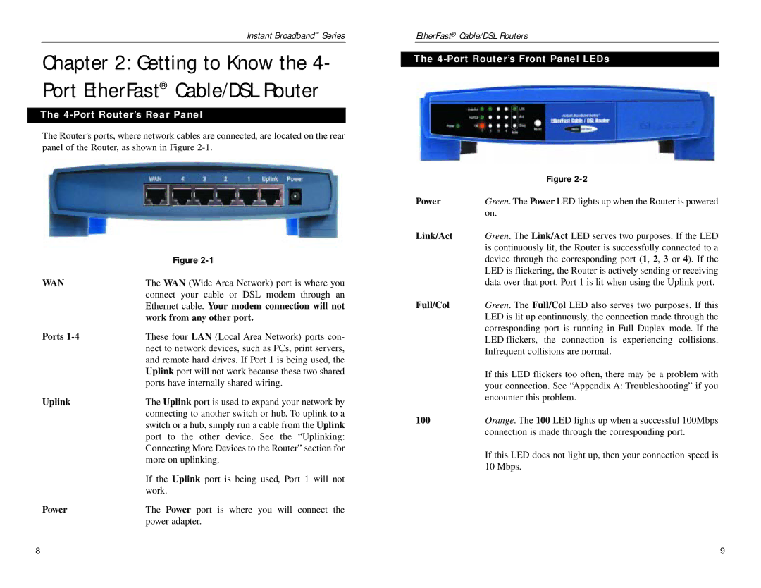
The Linksys BEPSR series, which includes the BEPSR41, BEPSR11, and BEPSR31 models, is renowned for its commitment to providing robust, reliable networking solutions for both home and small office environments. Each model in this line features distinctive characteristics that suit different needs while maintaining the core performance that Linksys is known for.The Linksys BEPSR41 is a four-port broadband router that stands out for its exceptional speed and stability. With support for ADSL and cable connections, this model is equipped with advanced features such as Network Address Translation (NAT) and a built-in firewall for enhanced security. The BEPSR41 utilizes wired Ethernet technology, providing reliable connections and lag-free access to the internet. Its four LAN ports enable connections to multiple devices, making it an ideal choice for households with numerous connected devices.
Moving on to the Linksys BEPSR11, this model is a more compact solution, designed for users with simpler networking needs. The BEPSR11 features a one-port configuration, making it perfect for individual users or small setups that require minimal device connectivity. Despite its smaller size, it offers solid performance with similar NAT and firewall capabilities as its larger counterpart. This model is an excellent choice for users who value simplicity and efficient internet connectivity without the complexities of advanced networking setups.
Lastly, the Linksys BEPSR31 combines features from both previous models, offering an ideal balance between performance and usability. It provides two LAN ports, making it suitable for small offices or homes where a couple of wired connections are needed. The setup process is straightforward, allowing users to get online quickly with minimal configuration. The BEPSR31 also supports basic QoS (Quality of Service) features, allowing users to prioritize traffic for smoother streaming and gaming experiences.
All three models emphasize ease of use, security, and dependable performance, catering to different user requirements. Their solid design, combined with Linksys’s reputation for quality and reliability in home networking, makes the BEPSR41, BEPSR11, and BEPSR31 excellent options for anyone looking to enhance their internet experience without extensive technical knowledge. Whether for gaming, streaming, or everyday browsing, these routers provide essential features that meet modern connectivity demands.

