BLOWER THREE
PRONGED PLUG TO
GROUNDED OUTLET
Figure 44
The FBK-100/200 Blower Kits are design cer- tified by Warnock Hersey for use with these appliances.
Always check local building codes. Installation of the FBK Blower Kits must comply with local regulations as well as the National Electric Code.
Combustion Air Kits
These appliances are equipped with an outside (make-up) air door and integral actuator arm. If the appliance is to be installed with an outside air vent system, use only FireCraft Models FAOK-4 or FAOK-4LD Combustion Air Kits. These kits come complete with detailed installation instruc- tions and all components necessary in complet- ing a combustion air vent system.
After completing the installation of the optional combustion air vent system the actuator arm must be put in service and tested to ensure proper operation before completing any enclo- sure around the firebox. Failure to do so may result in extensive and costly rework.
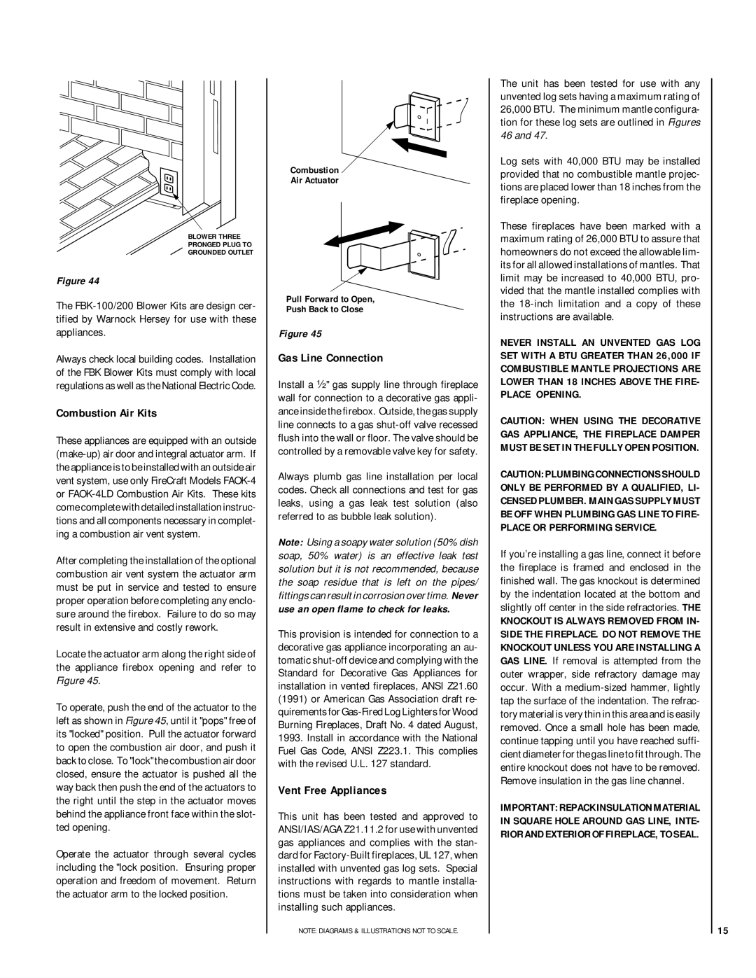
Locate the actuator arm along the right side of the appliance firebox opening and refer to Figure 45.
To operate, push the end of the actuator to the left as shown in Figure 45, until it "pops" free of its "locked" position. Pull the actuator forward to open the combustion air door, and push it back to close. To "lock" the combustion air door closed, ensure the actuator is pushed all the way back then push the end of the actuators to the right until the step in the actuator moves behind the appliance front face within the slot- ted opening.
Operate the actuator through several cycles including the "lock position. Ensuring proper operation and freedom of movement. Return the actuator arm to the locked position.
Combustion 
Air Actuator
Pull Forward to Open,
Push Back to Close
Figure 45
Gas Line Connection
Install a ¹⁄₂" gas supply line through fireplace wall for connection to a decorative gas appli- ance inside the firebox. Outside, the gas supply line connects to a gas shut-off valve recessed flush into the wall or floor. The valve should be controlled by a removable valve key for safety.
Always plumb gas line installation per local codes. Check all connections and test for gas leaks, using a gas leak test solution (also referred to as bubble leak solution).
Note: Using a soapy water solution (50% dish soap, 50% water) is an effective leak test solution but it is not recommended, because the soap residue that is left on the pipes/ fittings can result in corrosion over time. Never use an open flame to check for leaks.
This provision is intended for connection to a decorative gas appliance incorporating an au- tomatic shut-off device and complying with the Standard for Decorative Gas Appliances for installation in vented fireplaces, ANSI Z21.60 (1991) or American Gas Association draft re- quirements for Gas-Fired Log Lighters for Wood Burning Fireplaces, Draft No. 4 dated August, 1993. Install in accordance with the National Fuel Gas Code, ANSI Z223.1. This complies with the revised U.L. 127 standard.
Vent Free Appliances
This unit has been tested and approved to ANSI/IAS/AGA Z21.11.2 for use with unvented gas appliances and complies with the stan- dard for Factory-Built fireplaces, UL 127, when installed with unvented gas log sets. Special instructions with regards to mantle installa- tions must be taken into consideration when installing such appliances.
NOTE: DIAGRAMS & ILLUSTRATIONS NOT TO SCALE.
The unit has been tested for use with any unvented log sets having a maximum rating of 26,000 BTU. The minimum mantle configura- tion for these log sets are outlined in Figures 46 and 47.
Log sets with 40,000 BTU may be installed provided that no combustible mantle projec- tions are placed lower than 18 inches from the fireplace opening.
These fireplaces have been marked with a maximum rating of 26,000 BTU to assure that homeowners do not exceed the allowable lim- its for all allowed installations of mantles. That limit may be increased to 40,000 BTU, pro- vided that the mantle installed complies with the 18-inch limitation and a copy of these instructions are available.
NEVER INSTALL AN UNVENTED GAS LOG SET WITH A BTU GREATER THAN 26,000 IF COMBUSTIBLE MANTLE PROJECTIONS ARE LOWER THAN 18 INCHES ABOVE THE FIRE- PLACE OPENING.
CAUTION: WHEN USING THE DECORATIVE GAS APPLIANCE, THE FIREPLACE DAMPER MUST BE SET IN THE FULLY OPEN POSITION.
CAUTION: PLUMBING CONNECTIONS SHOULD ONLY BE PERFORMED BY A QUALIFIED, LI- CENSED PLUMBER. MAIN GAS SUPPLY MUST BE OFF WHEN PLUMBING GAS LINE TO FIRE- PLACE OR PERFORMING SERVICE.
If you’re installing a gas line, connect it before the fireplace is framed and enclosed in the finished wall. The gas knockout is determined by the indentation located at the bottom and slightly off center in the side refractories. THE
KNOCKOUT IS ALWAYS REMOVED FROM IN- SIDE THE FIREPLACE. DO NOT REMOVE THE KNOCKOUT UNLESS YOU ARE INSTALLING A GAS LINE. If removal is attempted from the outer wrapper, side refractory damage may occur. With a medium-sized hammer, lightly tap the surface of the indentation. The refrac- tory material is very thin in this area and is easily removed. Once a small hole has been made, continue tapping until you have reached suffi- cient diameter for the gas line to fit through. The entire knockout does not have to be removed. Remove insulation in the gas line channel.
IMPORTANT: REPACK INSULATION MATERIAL IN SQUARE HOLE AROUND GAS LINE, INTE- RIOR AND EXTERIOR OF FIREPLACE, TO SEAL.
15