8

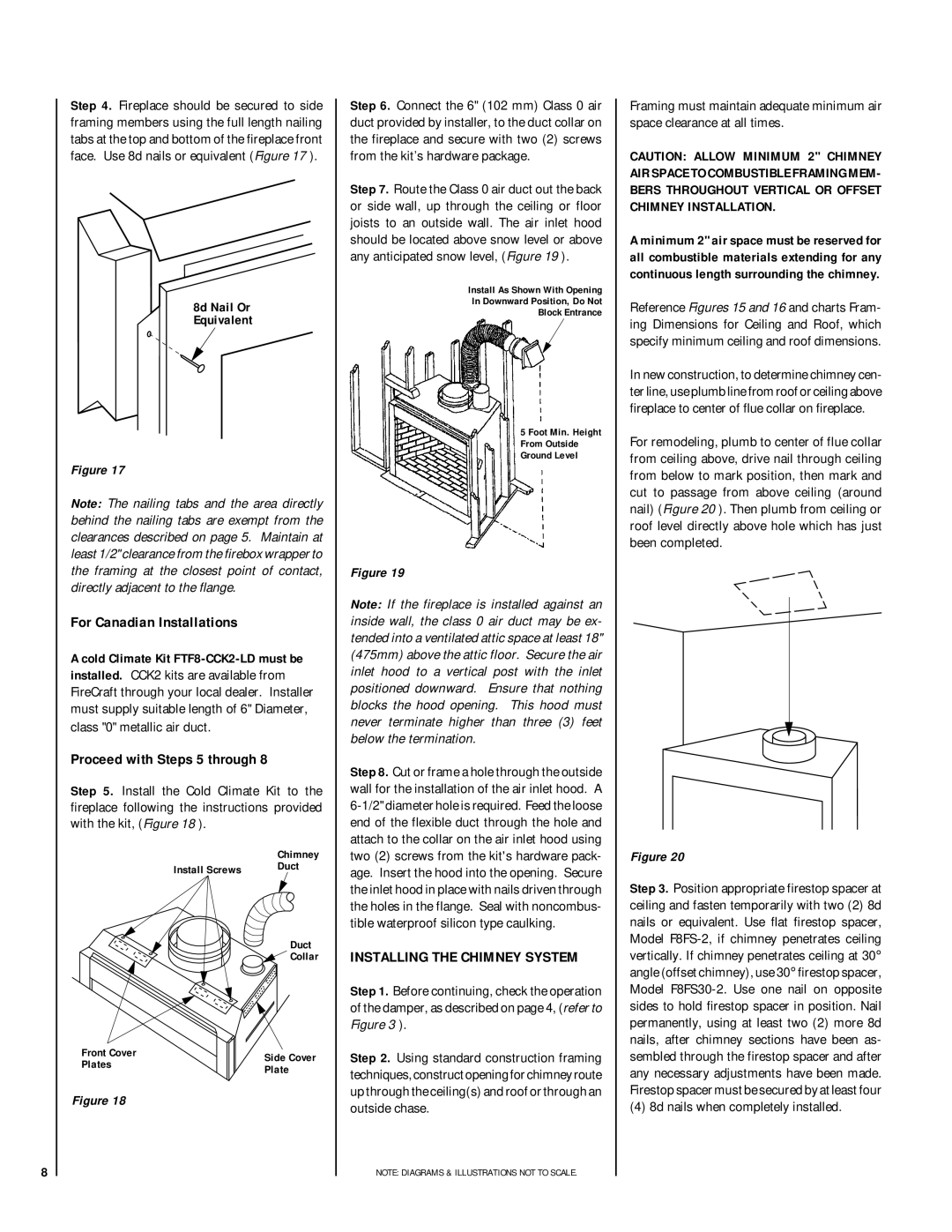
Step 4. Fireplace should be secured to side framing members using the full length nailing tabs at the top and bottom of the fireplace front face. Use 8d nails or equivalent (Figure 17 ).

8d Nail Or

Equivalent

Figure 17

Note: The nailing tabs and the area directly behind the nailing tabs are exempt from the clearances described on page 5. Maintain at least 1/2" clearance from the firebox wrapper to the framing at the closest point of contact, directly adjacent to the flange.

For Canadian Installations

A cold Climate Kit FTF8-CCK2-LD must be installed. CCK2 kits are available from FireCraft through your local dealer. Installer must supply suitable length of 6" Diameter, class "0" metallic air duct.

Proceed with Steps 5 through 8

Step 5. Install the Cold Climate Kit to the fireplace following the instructions provided with the kit, (Figure 18 ).


Chimney

Install Screws

Duct


Duct

Collar

Front Cover

Side Cover

Plates

Plate


Figure 18

Step 6. Connect the 6" (102 mm) Class 0 air duct provided by installer, to the duct collar on the fireplace and secure with two (2) screws from the kit’s hardware package.

Step 7. Route the Class 0 air duct out the back or side wall, up through the ceiling or floor joists to an outside wall. The air inlet hood should be located above snow level or above any anticipated snow level, (Figure 19 ).

Install As Shown With Opening

In Downward Position, Do Not

Block Entrance

5 Foot Min. Height

From Outside

Ground Level

Figure 19

Note: If the fireplace is installed against an inside wall, the class 0 air duct may be ex- tended into a ventilated attic space at least 18" (475mm) above the attic floor. Secure the air inlet hood to a vertical post with the inlet positioned downward. Ensure that nothing blocks the hood opening. This hood must never terminate higher than three (3) feet below the termination.

Step 8. Cut or frame a hole through the outside wall for the installation of the air inlet hood. A 6-1/2" diameter hole is required. Feed the loose end of the flexible duct through the hole and attach to the collar on the air inlet hood using two (2) screws from the kit's hardware pack- age. Insert the hood into the opening. Secure the inlet hood in place with nails driven through the holes in the flange. Seal with noncombus- tible waterproof silicon type caulking.

INSTALLING THE CHIMNEY SYSTEM

Step 1. Before continuing, check the operation of the damper, as described on page 4, (refer to Figure 3 ).

Step 2. Using standard construction framing techniques, construct opening for chimney route up through the ceiling(s) and roof or through an outside chase.

NOTE: DIAGRAMS & ILLUSTRATIONS NOT TO SCALE.

Framing must maintain adequate minimum air space clearance at all times.

CAUTION: ALLOW MINIMUM 2" CHIMNEY AIR SPACE TO COMBUSTIBLE FRAMING MEM- BERS THROUGHOUT VERTICAL OR OFFSET CHIMNEY INSTALLATION.

A minimum 2" air space must be reserved for all combustible materials extending for any continuous length surrounding the chimney.

Reference Figures 15 and 16 and charts Fram- ing Dimensions for Ceiling and Roof, which specify minimum ceiling and roof dimensions.

In new construction, to determine chimney cen- ter line, use plumb line from roof or ceiling above fireplace to center of flue collar on fireplace.

For remodeling, plumb to center of flue collar from ceiling above, drive nail through ceiling from below to mark position, then mark and cut to passage from above ceiling (around nail) (Figure 20 ). Then plumb from ceiling or roof level directly above hole which has just been completed.

Figure 20

Step 3. Position appropriate firestop spacer at ceiling and fasten temporarily with two (2) 8d nails or equivalent. Use flat firestop spacer, Model F8FS-2, if chimney penetrates ceiling vertically. If chimney penetrates ceiling at 30° angle (offset chimney), use 30° firestop spacer, Model F8FS30-2. Use one nail on opposite sides to hold firestop spacer in position. Nail permanently, using at least two (2) more 8d nails, after chimney sections have been as- sembled through the firestop spacer and after any necessary adjustments have been made. Firestop spacer must be secured by at least four

(4) 8d nails when completely installed.

Page 8
Image 8
Linksys RDI-36-H HCI-36-H For Canadian Installations, Proceed with Steps 5 through, Installing the Chimney System

RDI-36-H HCI-36-H specifications

Linksys RDI-36-H HCI-36-H is a robust router designed for delivering reliable and high-performance network connectivity. Geared towards both home users and small businesses, this device integrates advanced technologies to ensure efficient data transmission and an enhanced user experience.

One of the standout features of the Linksys RDI-36-H HCI-36-H is its dual-band capability. Operating on both the 2.4 GHz and 5 GHz frequency bands, the router allows devices to connect to the less congested 5 GHz band for higher speeds, while the 2.4 GHz band provides extended range. This dual-band functionality helps minimize interference and maximizes bandwidth, making it ideal for streaming HD videos, online gaming, and other bandwidth-intensive applications.

The router is equipped with MU-MIMO (Multi-User, Multiple Input, Multiple Output) technology, which enables it to communicate with multiple devices simultaneously. This means that users can enjoy a more stable and faster connection even when numerous devices are connected at the same time. Additionally, the RDI-36-H HCI-36-H supports Beamforming technology, which focuses the Wi-Fi signal directly towards connected devices rather than just broadcasting it uniformly. This enhances connection quality and range, ensuring users experience fewer drops and interruptions.

Another significant feature of the Linksys RDI-36-H HCI-36-H is its comprehensive security features that include WPA2 encryption, ensuring that users’ data is protected from unauthorized access. Furthermore, the device offers parental controls that allow users to manage internet access for specific devices, making it easier to ensure safe browsing for children.

The router also features Gigabit Ethernet ports, providing ultra-fast wired connections for devices such as gaming consoles, smart TVs, and computers. This ensures optimal performance for bandwidth-heavy activities, reducing latency and enhancing overall user experience.

Setup and management of the Linksys RDI-36-H HCI-36-H is facilitated through a user-friendly web interface and mobile app, allowing users to customize settings and monitor network activity conveniently.

In summary, the Linksys RDI-36-H HCI-36-H is a feature-rich router that combines dual-band technology, MU-MIMO, Beamforming, and robust security features to meet the demands of modern users. Its ability to support multiple devices seamlessly while providing fast, reliable connections makes it an excellent choice for anyone looking to enhance their home or small office network.