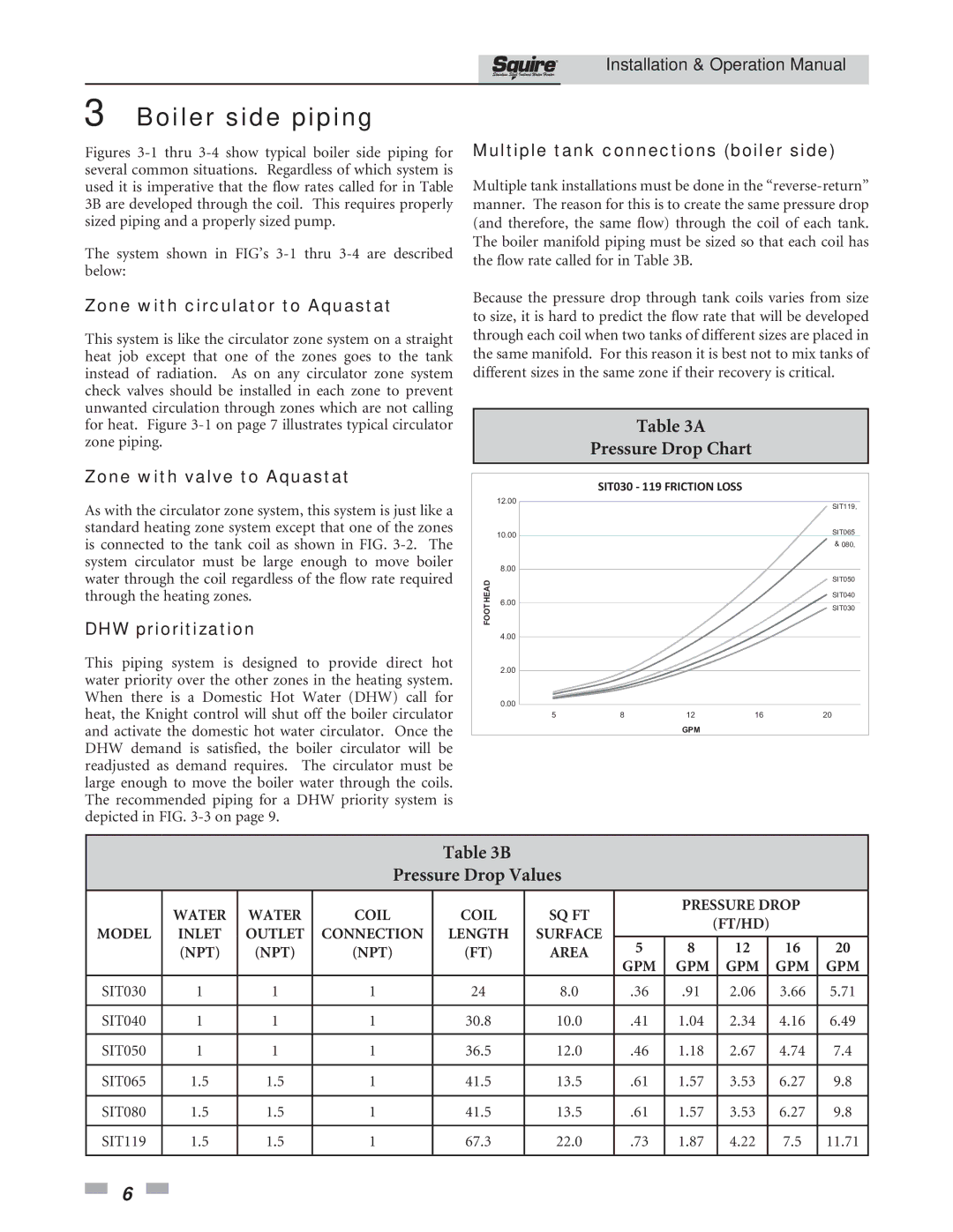
SIT030, SIT119 specifications
Lochinvar is a renowned manufacturer of high-efficiency heating solutions, including a range of commercial and residential boilers. Among their offerings are the Lochinvar SIT119 and SIT030 models, which exemplify the brand's commitment to innovation and efficiency in modern heating systems.The Lochinvar SIT119 is designed for medium to large residential applications, boasting a powerful heating capacity. This model features a robust stainless steel heat exchanger that not only enhances durability but also promotes optimal heat transfer. As part of Lochinvar’s commitment to energy efficiency, the SIT119 incorporates advanced features such as a modulating burner system that adjusts the flame output based on the heating demand, resulting in lower energy consumption and reduced operational costs.
In addition to its efficiency, the SIT119 is equipped with user-friendly controls that allow homeowners and technicians to easily manage and monitor the system. Its intuitive digital display provides real-time information on system performance and diagnostic capabilities, facilitating maintenance and troubleshooting. Furthermore, the SIT119’s compact design enables versatile installation options, making it suitable for various residential spaces.
On the other hand, the Lochinvar SIT030 is tailored for smaller residential applications. Despite its smaller size, it doesn’t compromise on performance or efficiency. This model also features a high-quality stainless steel heat exchanger, ensuring longevity and consistent heating performance. Like the SIT119, the SIT030 utilizes a modulating burner system to optimize energy use, making it an environmentally friendly choice for homeowners seeking effective heating solutions.
One notable characteristic of the SIT030 is its low NOx emission design, which aligns with contemporary environmental standards and helps reduce the carbon footprint associated with heating. Additionally, both models support easy integration with existing heating systems and can be paired with renewable energy sources, such as solar thermal systems, maximizing their efficiency and sustainability.
In summary, the Lochinvar SIT119 and SIT030 models stand out in the heating market, combining advanced technologies with high efficiency and user-friendly features. Their stainless steel construction, modulating burners, compact design, and emissions compliance make them excellent choices for homeowners looking to invest in reliable and eco-conscious heating solutions. With these models, Lochinvar continues to lead in producing innovative products that meet the evolving demands of the heating industry.