LK7000 PROGRAMMABLE KEYBOARD SPECIFICATIONS
| MECHANICAL |
|
|
| PROGRAMMING THE KEYBOARD |
|
|
|
|
|
|
|
|
|
|
|
|
|
| |
| Weight |
|
|
| 1.Use the utility software supplied to program up to |
|
|
|
| |||||||||||
| Basic Unit |
| 2.5lbs. |
| 256 alphanumeric characters per key. Utility |
|
|
|
| |||||||||||
| with MSR |
| 2.7lbs. |
| program will write to and read from computer disk | |||||||||||||||
| with Scanner |
| 2.6lbs. |
| memory. |
|
|
|
|
|
|
|
|
|
|
|
|
|
|
|
| Dimension (in inches) | STD | w/MSR |
| 2. Keyboard supports computer control keys (Shift, |
|
|
|
| |||||||||||
|
|
| CTRL, ALT, F1 through F12) and all arrow keys). |
|
|
|
| |||||||||||||
| Width | 15.7 | 15.7 |
|
|
|
|
|
|
|
|
|
|
|
|
|
|
|
|
|
| Depth | 8.5 | 9.0 |
|
|
|
|
|
|
|
|
|
|
|
|
|
|
|
|
|
| Front Height | 0.5 | 0.5 |
|
|
|
|
|
|
|
|
|
|
|
|
|
|
|
| |
|
| CONNECTOR PINOUTS |
|
|
|
|
|
|
|
|
|
|
|
|
|
| ||||
| Rear Height | 1.8 | 3.0 |
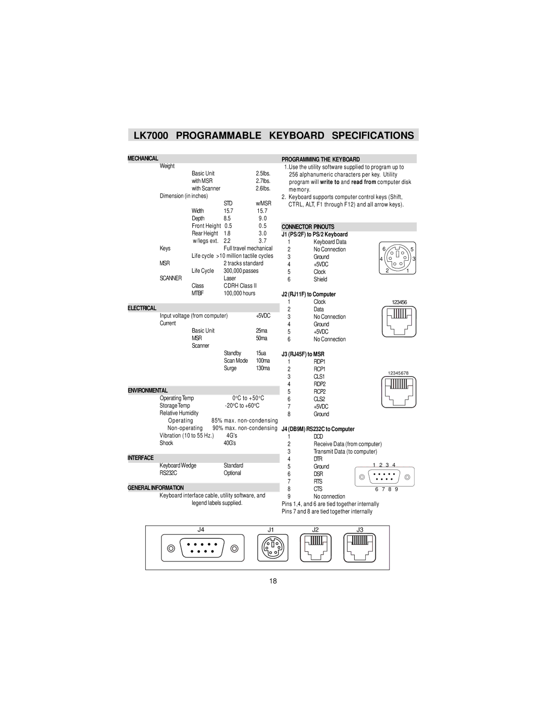
| J1 (PS/2F) to PS/2 Keyboard |
|
|
|
|
|
|
|
|
|
|
|
|
|
| |
| w/legs ext. | 2.2 | 3.7 | 1 | Keyboard Data |
|
|
|
|
|
|
|
|
|
|
|
|
|
| |
| Keys | Full travel mechanical | 2 | No Connection | 6 |
|
|
|
|
|
|
|
|
| 5 | |||||
| Life cycle >10 million tactile cycles | 3 | Ground | 4 |
|
|
|
|
|
|
|
|
| 3 | ||||||
| MSR | 2 tracks standard | 4 | +5VDC |
|
|
|
|
|
|
|
|
| |||||||
|
|
|
|
|
|
|
|
|
|
|
|
|
|
| ||||||
| Life Cycle | 300,000 passes | 5 | Clock |
| 2 |
|
|
|
|
|
|
| 1 |
| |||||
| SCANNER | Laser |
| 6 | Shield |
|
|
|
|
|
|
|
|
|
|
|
|
|
| |
| Class | CDRH Class II |
|
|
|
|
|
|
|
|
|
|
|
|
|
|
|
|
| |
| MTBF | 100,000 hours |
|
| J2 (RJ11F) to Computer |
|
|
|
|
|
|
|
|
|
|
|
|
|
| |
|
|
|
| 1 | Clock |
| 123456 |
|
|
| ||||||||||
| ELECTRICAL |
|
| 2 | Data |
|
|
|
|
|
|
|
|
|
|
|
|
|
| |
| Input voltage (from computer) | +5VDC | 3 | No Connection |
|
|
|
|
|
|
|
|
|
|
|
|
|
| ||
| Current |
|
| 4 | Ground |
|
|
|
|
|
|
|
|
|
|
|
|
|
| |
| Basic Unit |
| 25ma | 5 | +5VDC |
|
|
|
|
|
|
|
|
|
|
|
|
|
| |
| MSR |
| 50ma | 6 | No Connection |
|
|
|
|
|
|
|
|
|
|
|
|
|
| |
| Scanner |
|
|
|
|
|
|
|
|
|
|
|
|
|
|
|
|
|
|
|
|
| Standby | 15ua |
|
| Scan Mode | 100ma |
|
| Surge | 130ma |
|
|
|
|
ENVIRONMENTAL |
|
|
|
Operating Temp |
| 0oC to +50oC | |
Storage Temp |
| ||
Relative Humidity |
|
|
|
Operating | 85% max. | ||
90% max. | |||
Vibration (10 to 55 Hz.) | 4G's |
| |
Shock |
| 40G's |
|
|
|
|
|
INTERFACE |
|
|
|
Keyboard Wedge |
| Standard |
|
RS232C |
| Optional |
|
GENERALINFORMATION
Keyboard interface cable, utility software, and legend labels supplied.
J3 (RJ45F) to MSR
1RDP1
2RCP1
3 | CLS1 | 12345678 | |||||||||
|
|
|
|
|
|
|
|
|
| ||
4 | RDP2 |
|
|
|
|
|
|
|
|
|
|
5 | RCP2 |
|
|
|
|
|
|
|
|
|
|
6 | CLS2 |
|
|
|
|
|
|
|
|
|
|
|
|
|
|
|
|
|
|
|
| ||
7+5VDC
8Ground
J4 (DB9M) RS232C to Computer
1DCD
2Receive Data (from computer)
3Transmit Data (to computer)
4DTR
5 | Ground | 1 | 2 | 3 | 4 |
6 | DSR |
|
|
|
|
7 | RTS |
|
|
|
|
8 | CTS | 6 | 7 | 8 | 9 |
9 | No connection |
|
|
|
|
Pins 1,4, and 6 are tied together internally
Pins 7 and 8 are tied together internally
J4 | J1 |
|
|
| J2 |
|
|
|
|
|
|
|
| J3 |
|
|
|
| ||||||
|
|
|
|
|
|
|
|
|
|
|
|
|
|
|
|
|
|
|
|
|
|
|
|
|
|
|
|
|
|
|
|
|
|
|
|
|
|
|
|
|
|
|
|
|
|
|
|
|
|
|
|
|
|
|
|
|
|
|
|
|
|
|
|
|
|
|
|
|
|
|
|
|
|
|
|
|
|
|
|
|
|
|
|
|
|
|
|
|
|
|
|
|
|
|
|
|
|
|
|
|
|
|
|
|
|
|
|
|
|
|
|
|
|
|
|
|
|
|
|
|
|
|
|
|
18