PORTABLE COLOR LCD DIGITAL WIRELESS MONITORING SYSTEM
LW2002 Series - quick start guide
C. Power ON Camera and Receiver
About Digital Wireless
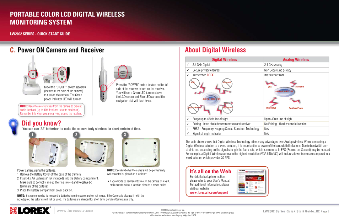
Move the “ON/OFF” switch upwards (located at the side of the camera) to turn on the camera. The Green power indicator LED will turn on.
NOTE: Keep the receiver away from the camera to prevent audio feedback (up to 10ft if volume is set to maximum). Remember this when you are carrying around the receiver.
Press the “POWER” button located on the left side of the receiver to turn on the receiver. You will see a Green LED turn on above
the LCD screen and Blue LEDs around the navigation dial will flash twice.
| Digital Wireless |
| Analog Wireless | |
| 2.4 GHz Digital |
| 2.4 GHz Analog |
|
|
|
|
| |
| Secure privacy ensured |
| Non Secure, no privacy | |
| Interference FREE |
| Interference from | |
| WiFi | Bluetooth |
|
|
|
|
| WiFi | Bluetooth |
|
|
| ANALOG WIRELESS | |
| DIGITAL WIRELESS |
|
|
|
Cordless Phone | Microwave | Microwave | Cordless Phone | |
Did you know?
You can use ‘AA’ batteries* to make the camera truly wireless for short periods of time.
1 |
| 2 |
| 3 |
|
|
|
|
|
Range up to 450 ft line of sight | Up to 300 ft line of sight | |
Pairing - hand shake between camera and receiver | No Pairing - fixed channel allocation | |
| FHSS - Frequency Hopping Spread Spectrum Technology | N/A |
| Signal strength Indicator | N/A |
The table above shows that Digital Wireless Technology offers many advantages over Analog wireless. When comparing a Digital Wireless solution to a wired solution, it is important to be aware of the bandwidth limitations. Due to bandwidth con- straints and depending on the signal strength the frame rate, which is measured in FPS (Frames per Second) may be reduced. For example, a Digital Wireless camera in the highest resolution (VGA 640x480) will feature a lower frame rate compared to a wired solution which provides 30 FPS.
Power camera using the batteries:
1.Remove the Battery Cover off the base of the Camera.
2.Insert 4 x AA Batteries (*not included) into the Battery compartment. Make sure to correctly line up the Positive (+) and Negative
3.Place the Battery compartment cover back on.
NOTE: Decide whether the camera will be permanently wall mounted or placed on a tabletop:
•If you decide to permanently mount the camera to a wall, make sure to select a location close to a power outlet.
It’s all on the Web
For detailed setup information, please refer to your User’s Manual. For additional information, please visit our website www.lorexcctv.com/support
NOTE: It is recommended to remove the batteries from the camera when not in use. If the Camera is plugged in with the AC Adaptor, the batteries will not be used. The batteries are intended for short term, portable Camera use only.
www.lorexcctv.com | ©2008 Lorex Technology Inc. |
| |
| As our product is subject to continuous improvement, Lorex Technology & subsidiaries reserve the right to modify product design, specifications & prices |
| without notice and without incurring any obligation. E&OE |
LW2002 Series Quick Start Guide_R2 Page