Reference Manual D AD 3220 B Version 1.0
Functional Diagram
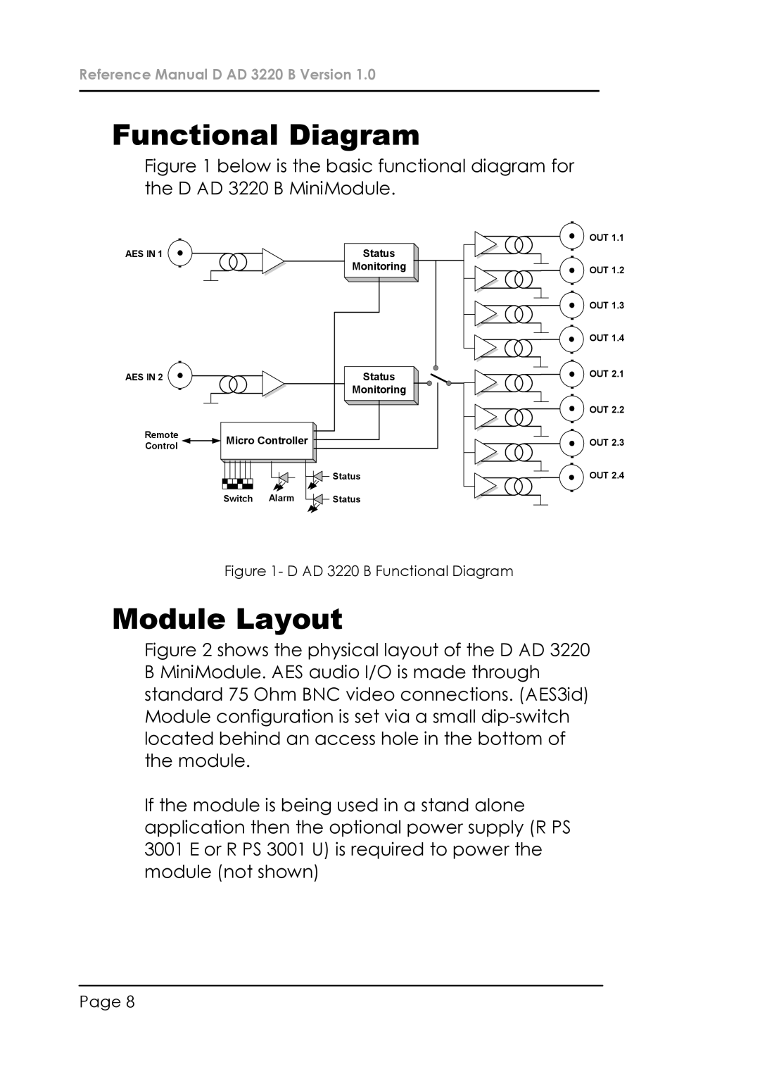
Figure 1 below is the basic functional diagram for the D AD 3220 B MiniModule.
AES IN 1 | Status |
Monitoring
AES IN 2 |
|
| Status |
|
|
| Monitoring |
Remote | Micro Controller |
| |
Control |
| ||
|
|
| |
|
|
| Status |
| Switch | Alarm | Status |
![]()
![]() OUT 1.1
OUT 1.1
OUT 1.2
![]()
![]() OUT 1.3
OUT 1.3
OUT 1.4
![]()
![]() OUT 2.1
OUT 2.1
OUT 2.2 |
OUT 2.3 |
OUT 2.4
Figure 1- D AD 3220 B Functional Diagram
Module Layout
Figure 2 shows the physical layout of the D AD 3220 B MiniModule. AES audio I/O is made through standard 75 Ohm BNC video connections. (AES3id) Module configuration is set via a small dip-switch located behind an access hole in the bottom of the module.
If the module is being used in a stand alone application then the optional power supply (R PS 3001 E or R PS 3001 U) is required to power the module (not shown)
Page 8