CABLE BOX CONNECTIONS
If you have a Cable Box, follow either set of
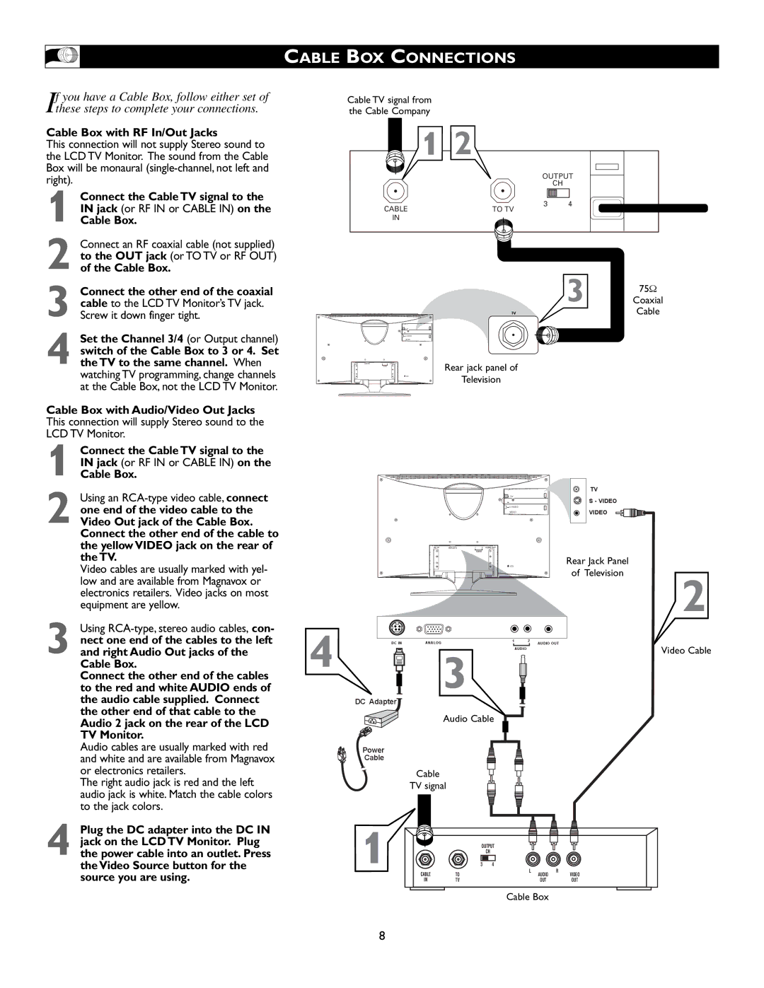
these steps to complete your connections.
Cable TV signal from the Cable Company
Cable Box with RF In/Out Jacks
This connection will not supply Stereo sound to the LCD TV Monitor. The sound from the Cable Box will be monaural
1
2
3
4 Set the Channel 3/4 (or Output channel) switch of the Cable Box to 3 or 4. Set the TV to the same channel. When watching TV programming, change channels at the Cable Box, not the LCD TV Monitor.
| 1 2 |
|
| OUTPUT | |
|
| CH |
CABLE | 3 | 4 |
TO TV |
| |
IN |
|
|
3 | 75Ω |
Coaxial | |
TV | Cable |
TV
VIDEO
DC IN ANALOG1 2
Rear jack panel of
Television
Cable Box with Audio/Video Out Jacks
This connection will supply Stereo sound to the
LCD TV Monitor.
Connect the Cable TV signal to the |
|
|
|
|
|
|
|
IN jack (or RF IN or CABLE IN) on the |
|
|
|
|
|
|
|
1 Cable Box. |
|
|
|
|
|
|
|
Using an |
|
|
|
|
|
| TV |
|
|
|
| TV |
| S - VIDEO | |
one end of the video cable to the |
|
|
|
|
| VIDEO | |
2 Video Out jack of the Cable Box. |
|
|
|
|
|
| |
|
|
|
| VIDEO |
|
| |
|
|
|
|
|
|
| |
Connect the other end of the cable to |
|
|
|
|
|
|
|
the yellow VIDEO jack on the rear of |
|
| DC IN ANALOG | AUDIO | AUDIO OUT |
|
|
|
|
| 1 2 |
|
| ||
the TV. |
|
|
|
|
|
| Rear Jack Panel |
Video cables are usually marked with yel- |
|
|
|
|
|
| |
|
|
|
|
|
| of Television | |
low and are available from Magnavox or |
|
|
|
|
|
| |
|
|
|
|
|
| 2 | |
electronics retailers. Video jacks on most |
|
|
|
|
|
| |
|
|
|
|
|
|
| |
equipment are yellow. |
|
|
|
|
|
|
|
Using |
|
|
|
|
|
|
|
nect one end of the cables to the left |
| DC IN | ANALOG |
|
|
| AUDIO OUT |
3 and right Audio Out jacks of the | 4 |
|
|
| 1 | 2 | Video Cable |
| 3 |
| AUDIO |
| |||
Cable Box. |
|
|
|
|
| ||
Connect the other end of the cables |
|
|
|
|
|
| |
to the red and white AUDIO ends of |
|
|
|
|
|
| |
the audio cable supplied. Connect |
| DC Adapter |
|
|
|
|
|
the other end of that cable to the |
|
| Audio Cable |
|
| ||
Audio 2 jack on the rear of the LCD |
|
|
|
| |||
|
|
|
|
|
|
| |
TV Monitor. |
|
|
|
|
|
|
|
Audio cables are usually marked with red |
| Power |
|
|
|
|
|
and white and are available from Magnavox |
| Cable |
|
|
|
|
|
or electronics retailers. |
|
| Cable |
|
|
|
|
The right audio jack is red and the left |
|
| TV signal |
|
|
|
|
audio jack is white. Match the cable colors |
|
|
|
|
|
|
|
to the jack colors. |
|
|
|
|
|
|
|
Plug the DC adapter into the DC IN |
|
jack on the LCD TV Monitor. Plug |
|
4 the power cable into an outlet. Press | 1 |
the Video Source button for the |
source you are using.
OUTPUT
CH
| 3 | 4 |
|
|
|
CABLE | TO | L | AUDIO | R | VIDEO |
|
| ||||
IN | TV |
| OUT |
| OUT |
Cable Box
8