P 4/10
 Repair
[3]DISASSEMBLY/ASSEMBLY
[3]-2. Base Complete (cont.)
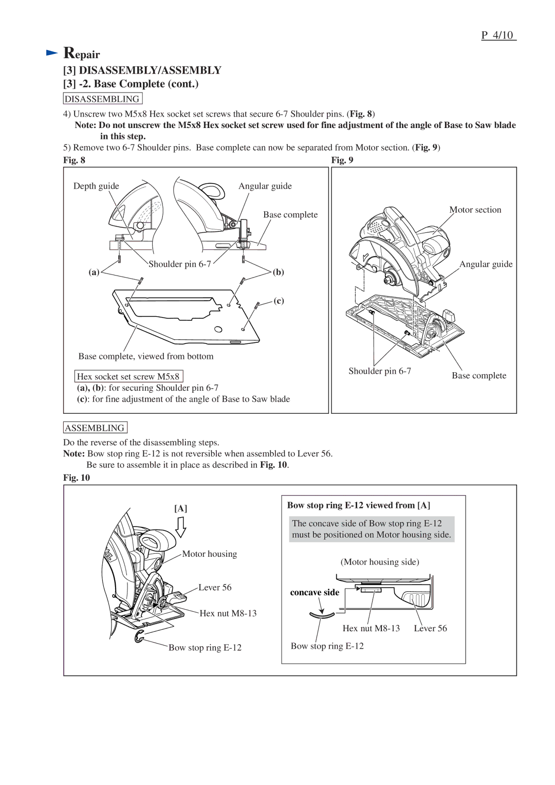
DISASSEMBLING
4) Unscrew two M5x8 Hex socket set screws that secure
Note: Do not unscrew the M5x8 Hex socket set screw used for fine adjustment of the angle of Base to Saw blade in this step.
5) Remove two
Fig. 8 | Fig. 9 |
Depth guide | Angular guide |
Base complete | Motor section |
|
Shoulder pin | Angular guide |
(a) | (b) |
| (c) |
Base complete, viewed from bottom |
|
| |
|
| Shoulder pin | Base complete |
Hex socket set screw M5x8 |
| ||
|
| ||
(a), (b): for securing Shoulder | pin |
|
|
(c): for fine adjustment of the angle of Base to Saw blade |
|
| |
ASSEMBLING
Do the reverse of the disassembling steps.
Note: Bow stop ring
Be sure to assemble it in place as described in Fig. 10.
Fig. 10
[A]
Motor housing
Lever 56
![]()
![]()
![]()
![]()
![]()
![]()
![]()
![]() Hex nut
Hex nut
Bow stop ring
Bow stop ring E-12 viewed from [A]
The concave side of Bow stop ring
(Motor housing side)
concave side
Hex nut
Bow stop ring