P 5/10
 Repair
[3]DISASSEMBLY/ASSEMBLY
[3]-3. Motor Section
DISASSEMBLING
After removing Safety cover, disassemble Motor section as described below;
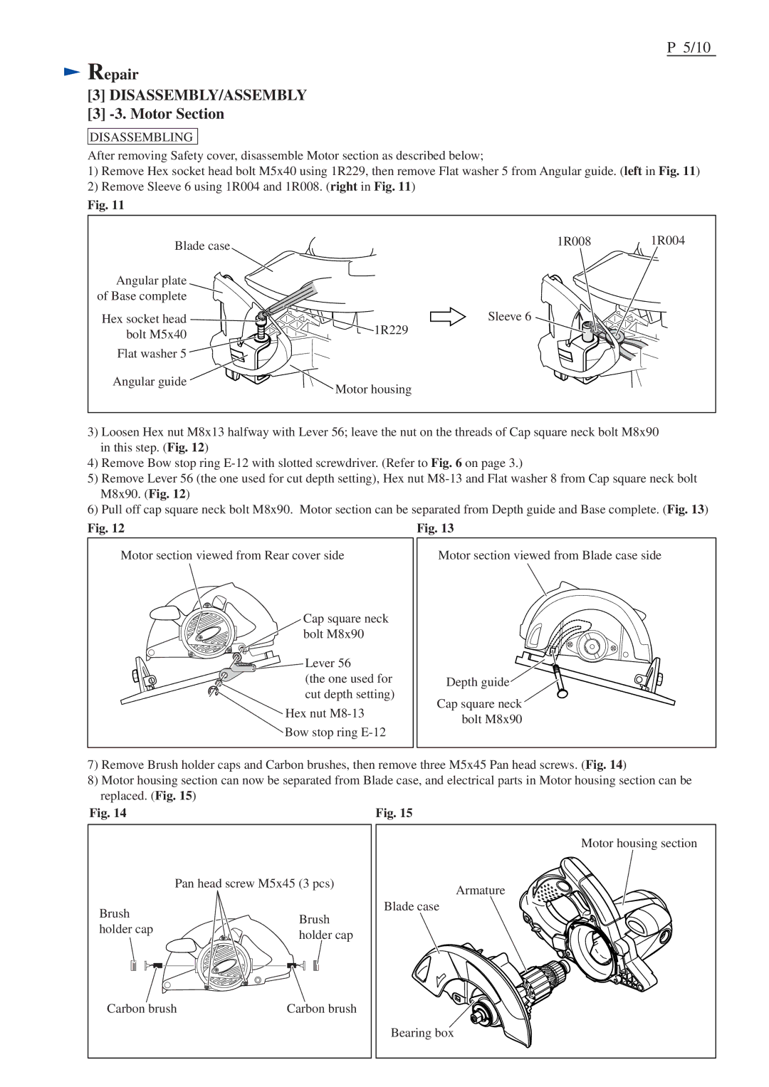
1)Remove Hex socket head bolt M5x40 using 1R229, then remove Flat washer 5 from Angular guide. (left in Fig. 11)
2)Remove Sleeve 6 using 1R004 and 1R008. (right in Fig. 11)
Fig. 11
Blade case | 1R008 | 1R004 |
|
| |
Angular plate |
|
|
of Base complete |
|
|
Hex socket head | Sleeve 6 |
|
bolt M5x40 | 1R229 |
|
|
| |
Flat washer 5 |
|
|
Angular guide | Motor housing |
|
|
|
3)Loosen Hex nut M8x13 halfway with Lever 56; leave the nut on the threads of Cap square neck bolt M8x90 in this step. (Fig. 12)
4)Remove Bow stop ring
5)Remove Lever 56 (the one used for cut depth setting), Hex nut
6)Pull off cap square neck bolt M8x90. Motor section can be separated from Depth guide and Base complete. (Fig. 13)
Fig. 12
Motor section viewed from Rear cover side
Cap square neck bolt M8x90
Lever 56 |
(the one used for |
cut depth setting) |
Hex nut
Bow stop ring
Fig. 13
Motor section viewed from Blade case side
Depth guide![]()
Cap square neck bolt M8x90
7)Remove Brush holder caps and Carbon brushes, then remove three M5x45 Pan head screws. (Fig. 14)
8)Motor housing section can now be separated from Blade case, and electrical parts in Motor housing section can be replaced. (Fig. 15)
Fig. 14
| Pan head screw M5x45 (3 pcs) | |
Brush | Brush | |
holder cap | ||
holder cap | ||
|
Carbon brush | Carbon brush |
Fig. 15
Motor housing section
Armature
Blade case
Bearing box