P 6/ 8
![]() Wiring diagram
Wiring diagram
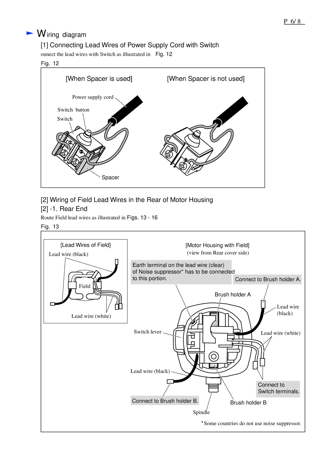
[1] Connecting Lead Wires of Power Supply Cord with Switch
Connect the lead wires with Switch as illustrated in Fig. 12.
Fig. 12
[When Spacer is used] | [When Spacer is not used] |
Power supply cord |
|
Switch button |
|
Switch |
|
Spacer |
|
[2]Wiring of Field Lead Wires in the Rear of Motor Housing
[2]
Route Field lead wires as illustrated in Figs. 13 - 16.
Fig. 13
[Lead Wires of Field] |
Lead wire (black) |
Field |
Lead wire (white) |
[Motor Housing with Field] (view from Rear cover side)
Earth terminal on the lead wire (clear) |
|
of Noise suppressor* has to be connected |
|
to this portion. | Connect to Brush holder A. |
Brush holder A
Lead wire (black)
Switch lever | Lead wire (white) |
Lead wire (black)
|
|
|
|
|
| Connect to |
|
|
|
|
|
| |
|
|
|
|
|
| |
|
|
|
|
|
| Switch terminals. |
|
|
|
|
|
| |
|
|
|
|
|
|
|
Connect to Brush holder B. |
|
|
|
| ||
|
| Brush holder B | ||||
|
|
|
|
| ||
Spindle
*Some countries do not use noise suppressor.