P 10/ 10
Repair
[3]ASSEMBLING/ DISASSEMBLING
[3]-8. Door cover section
ASSEMBLING
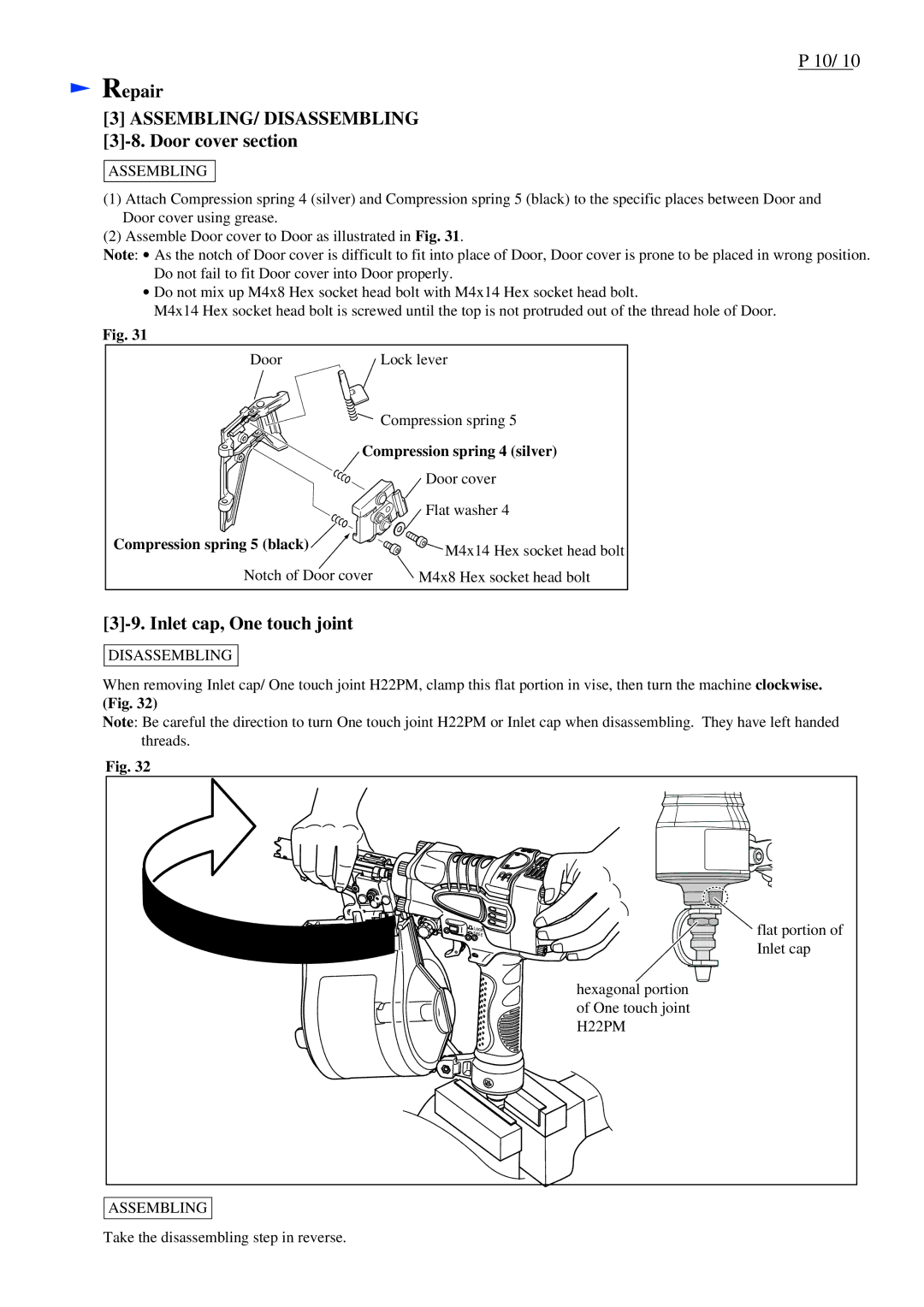
(1)Attach Compression spring 4 (silver) and Compression spring 5 (black) to the specific places between Door and Door cover using grease.
(2)Assemble Door cover to Door as illustrated in Fig. 31.
Note: ![]() As the notch of Door cover is difficult to fit into place of Door, Door cover is prone to be placed in wrong position. Do not fail to fit Door cover into Door properly.
As the notch of Door cover is difficult to fit into place of Door, Door cover is prone to be placed in wrong position. Do not fail to fit Door cover into Door properly.
![]() Do not mix up M4x8 Hex socket head bolt with M4x14 Hex socket head bolt.
Do not mix up M4x8 Hex socket head bolt with M4x14 Hex socket head bolt.
M4x14 Hex socket head bolt is screwed until the top is not protruded out of the thread hole of Door.
Fig. 31
Door | Lock lever |
| Compression spring 5 |
Compression spring 4 (silver) | |
| Door cover |
| Flat washer 4 |
Compression spring 5 (black) | M4x14 Hex socket head bolt |
| |
Notch of Door cover | M4x8 Hex socket head bolt |
[3]-9. Inlet cap, One touch joint
DISASSEMBLING
When removing Inlet cap/ One touch joint H22PM, clamp this flat portion in vise, then turn the machine clockwise. (Fig. 32)
Note: Be careful the direction to turn One touch joint H22PM or Inlet cap when disassembling. They have left handed threads.
Fig. 32
![]()
![]()
![]()
![]()
![]()
![]()
![]() flat portion of
flat portion of
Inlet cap
hexagonal portion of One touch joint H22PM
ASSEMBLING
Take the disassembling step in reverse.
