Repair
[3]ASSEMBLING/ DISASSEMBLING [3]-3. Magazine section (cont.)
ASSEMBLING
| P 6/ 10 |
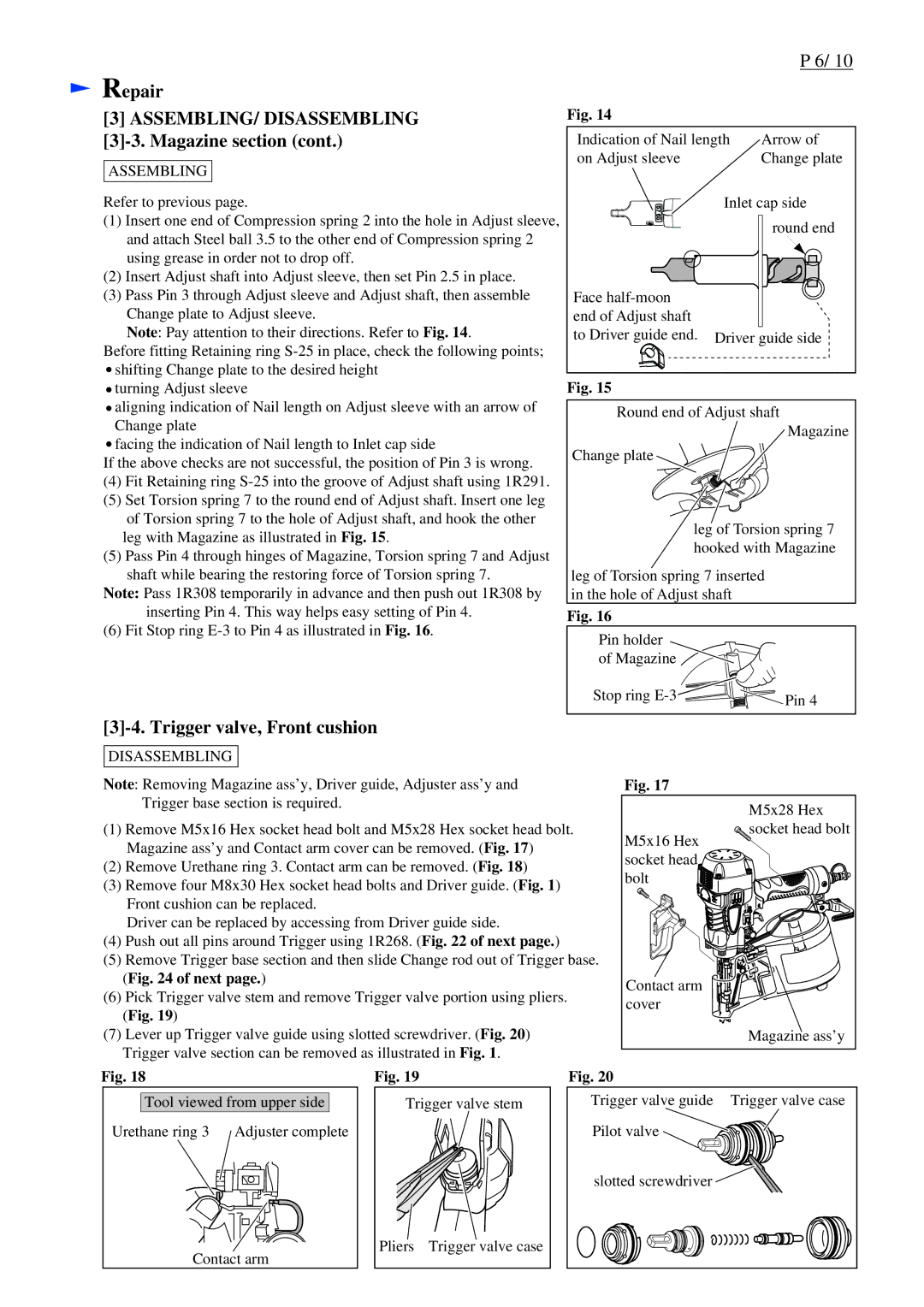
Fig. 14 |
|
|
|
Indication of Nail length | Arrow of |
on Adjust sleeve | Change plate |
Refer to previous page.
(1)Insert one end of Compression spring 2 into the hole in Adjust sleeve, and attach Steel ball 3.5 to the other end of Compression spring 2 using grease in order not to drop off.
(2)Insert Adjust shaft into Adjust sleeve, then set Pin 2.5 in place.
(3)Pass Pin 3 through Adjust sleeve and Adjust shaft, then assemble Change plate to Adjust sleeve.
Note: Pay attention to their directions. Refer to Fig. 14.
Before fitting Retaining ring ![]() shifting Change plate to the desired height
shifting Change plate to the desired height
Face
Inlet cap side round end
Driver guide side
![]() turning Adjust sleeve
turning Adjust sleeve
![]() aligning indication of Nail length on Adjust sleeve with an arrow of Change plate
aligning indication of Nail length on Adjust sleeve with an arrow of Change plate
![]() facing the indication of Nail length to Inlet cap side
facing the indication of Nail length to Inlet cap side
If the above checks are not successful, the position of Pin 3 is wrong.
(4)Fit Retaining ring
(5)Set Torsion spring 7 to the round end of Adjust shaft. Insert one leg
of Torsion spring 7 to the hole of Adjust shaft, and hook the other leg with Magazine as illustrated in Fig. 15.
(5)Pass Pin 4 through hinges of Magazine, Torsion spring 7 and Adjust shaft while bearing the restoring force of Torsion spring 7.
Note: Pass 1R308 temporarily in advance and then push out 1R308 by inserting Pin 4. This way helps easy setting of Pin 4.
(6) Fit Stop ring
Fig. 15
Round end of Adjust shaft
Magazine
Change plate
leg of Torsion spring 7 hooked with Magazine
leg of Torsion spring 7 inserted in the hole of Adjust shaft
Fig. 16
Pin holder
of Magazine ![]()
![]()
![]()
Stop ring ![]()
![]()
![]() Pin 4
Pin 4
[3]-4. Trigger valve, Front cushion
DISASSEMBLING
Note: Removing Magazine ass’y, Driver guide, Adjuster ass’y and Trigger base section is required.
(1)Remove M5x16 Hex socket head bolt and M5x28 Hex socket head bolt. Magazine ass’y and Contact arm cover can be removed. (Fig. 17)
(2)Remove Urethane ring 3. Contact arm can be removed. (Fig. 18)
(3)Remove four M8x30 Hex socket head bolts and Driver guide. (Fig. 1) Front cushion can be replaced.
Driver can be replaced by accessing from Driver guide side.
(4)Push out all pins around Trigger using 1R268. (Fig. 22 of next page.)
(5)Remove Trigger base section and then slide Change rod out of Trigger base. (Fig. 24 of next page.)
(6)Pick Trigger valve stem and remove Trigger valve portion using pliers.
(Fig. 19)
(7)Lever up Trigger valve guide using slotted screwdriver. (Fig. 20) Trigger valve section can be removed as illustrated in Fig. 1.
Fig. 17
M5x28 Hex
socket head bolt
M5x16 Hex ![]()
![]() socket head
socket head ![]()
![]() bolt
bolt ![]()
![]()
![]()
![]()
![]()
![]()
![]()
Contact arm cover
Magazine ass’y
Fig. 18
Tool viewed from upper side
Urethane ring 3 |
|
|
| Adjuster complete | ||||||||||
|
|
|
|
|
|
|
|
|
|
|
|
|
|
|
|
|
|
|
|
|
|
|
|
|
|
|
|
|
|
|
|
|
|
|
|
|
|
|
|
|
|
|
|
|
|
|
|
|
|
|
|
|
|
|
|
|
|
|
|
|
|
|
|
|
|
|
|
|
|
|
|
|
|
|
|
|
|
|
|
|
|
|
|
|
|
|
|
|
|
|
|
|
|
|
|
|
|
|
|
|
|
|
|
|
|
|
|
|
|
|
|
|
|
|
|
|
|
|
|
|
|
|
|
|
|
|
|
|
|
|
|
|
|
|
|
|
|
|
|
|
|
|
|
|
|
|
|
|
|
|
|
|
|
|
|
|
|
|
|
|
|
|
|
|
|
|
|
|
|
|
|
|
|
|
|
|
|
|
|
Contact arm
Fig. 19
Trigger valve stem
Pliers Trigger valve case
Fig. 20
Trigger valve guide Trigger valve case Pilot valve ![]()
![]()
![]()
![]()
slotted screwdriver ![]()