P 2/ 12
![]() Repair
Repair
CAUTION: Repair the machine in accordance with “Instruction manual” or “Safety instructions”.
[1] NECESSARY REPAIRING TOOLS
Code No. | Description | Use for |
1R359 | Drill chuck removing tool | (Use this tool if Drill chuck cannot be removed by the method of |
described in | ||
| Hex wrench 10 | removing/ mounting Drill chuck |
[2] LUBRICATION
It is not required to lubricate the gear section because the portion is replaced as a
[3]DISASSEMBLY/ASSEMBLY
[3]-1. Drill Chuck
DISASSEMBLING
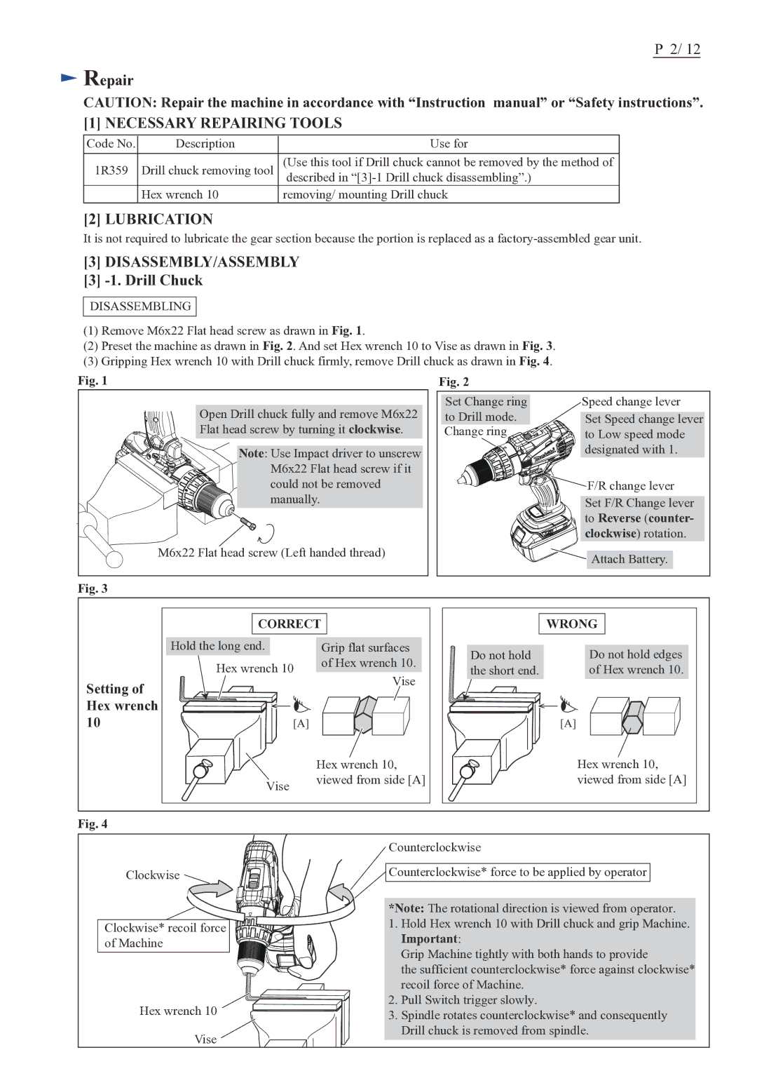
(1)Remove M6x22 Flat head screw as drawn in Fig. 1.
(2)Preset the machine as drawn in Fig. 2. And set Hex wrench 10 to Vise as drawn in Fig. 3.
(3)Gripping Hex wrench 10 with Drill chuck firmly, remove Drill chuck as drawn in Fig. 4.
Fig. 1
Open Drill chuck fully and remove M6x22
Flat head screw by turning it clockwise.
Note: Use Impact driver to unscrew
M6x22 Flat head screw if it could not be removed manually.
M6x22 Flat head screw (Left handed thread)
Fig. 2
Set Change ring | Speed change lever |
to Drill mode. | Set Speed change lever |
Change ring | to Low speed mode |
| designated with 1. |
| F/R change lever |
| Set F/R Change lever |
| to Reverse (counter- |
| clockwise) rotation. |
| Attach Battery. |
Fig. 3
| CORRECT |
| WRONG | |
| Hold the long end. | Grip flat surfaces | Do not hold | Do not hold edges |
| Hex wrench 10 | of Hex wrench 10. | ||
| the short end. | of Hex wrench 10. | ||
| Vise | |||
Setting of |
|
|
| |
|
|
|
| |
Hex wrench |
|
|
|
|
10 | [A] |
|
| [A] |
|
| Hex wrench 10, |
| Hex wrench 10, |
| Vise | viewed from side [A] |
| viewed from side [A] |
|
|
|
| |
Fig. 4
Clockwise ![]()
Clockwise* recoil force of Machine
Hex wrench 10 ![]()
![]()
Vise ![]()
Counterclockwise
Counterclockwise* force to be applied by operator
*Note: The rotational direction is viewed from operator.
1.Hold Hex wrench 10 with Drill chuck and grip Machine. Important:
Grip Machine tightly with both hands to provide
the sufficient counterclockwise* force against clockwise* recoil force of Machine.
2.Pull Switch trigger slowly.
3.Spindle rotates counterclockwise* and consequently Drill chuck is removed from spindle.
