P 14/ 14
 Wiring diagram
Fig. D-2
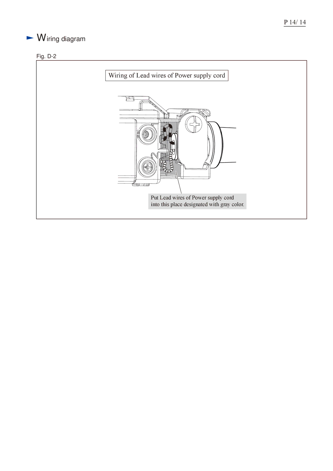
Wiring of Lead wires of Power supply cord
Put Lead wires of Power supply cord into this place designated with gray color.
P 14/ 14
Wiring of Lead wires of Power supply cord
Put Lead wires of Power supply cord into this place designated with gray color.