P 10/ 11
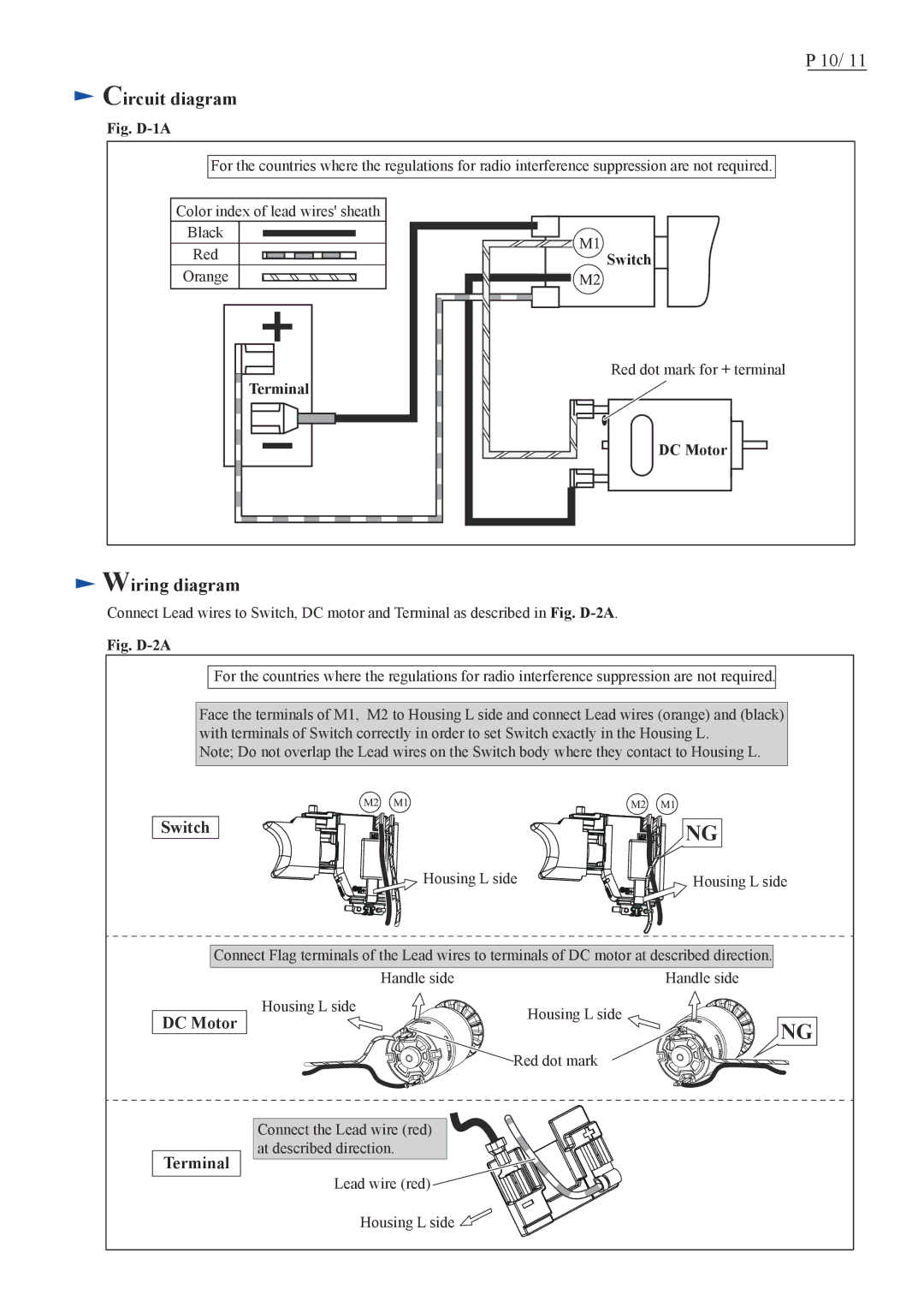
 Circuit diagram
Fig. D-1A
For the countries where the regulations for radio interference suppression are not required.
Color index of lead wires' sheath
Black |
Red |
Orange |
Terminal |
![]() Switch
Switch
Red dot mark for + terminal
DC Motor
 Wiring diagram
Connect Lead wires to Switch, DC motor and Terminal as described in Fig.
Fig. D-2A
For the countries where the regulations for radio interference suppression are not required.
Face the terminals of M1, M2 to Housing L side and connect Lead wires (orange) and (black) with terminals of Switch correctly in order to set Switch exactly in the Housing L.
Note; Do not overlap the Lead wires on the Switch body where they contact to Housing L.
Switch
NG
Housing L side | Housing L side |
Connect Flag terminals of the Lead wires to terminals of DC motor at described direction.
DC Motor
Handle side |
| Handle side |
Housing L side | Housing L side |
|
| NG | |
|
| |
| Red dot mark |
|
Terminal
Connect the Lead wire (red) at described direction.
Lead wire (red) ![]() Housing L side
Housing L side ![]()
