P 9/ 11
 Wiring diagram
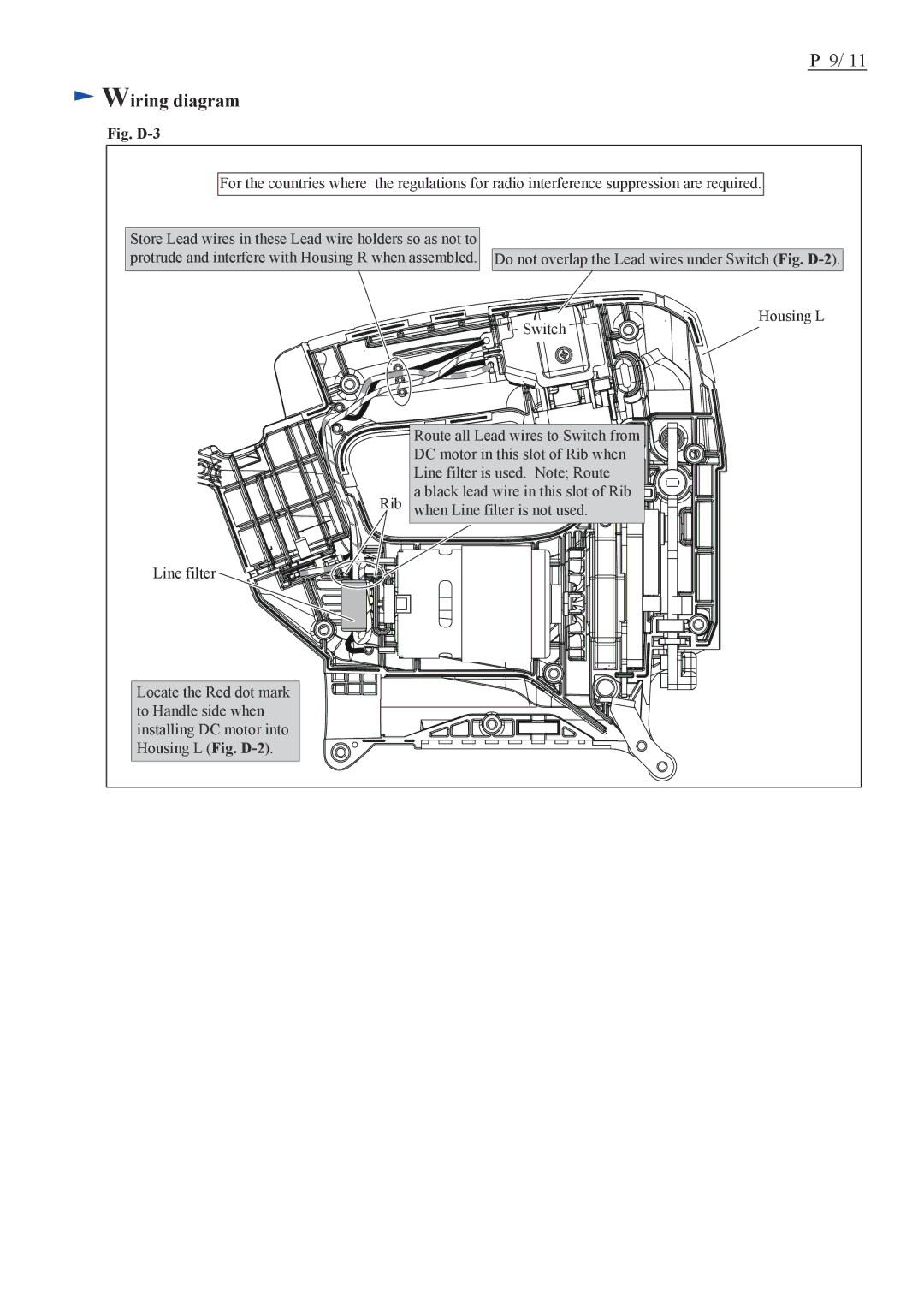
Fig. D-3
For the countries where the regulations for radio interference suppression are required.
Store Lead wires in these Lead wire holders so as not to protrude and interfere with Housing R when assembled.
Do not overlap the Lead wires under Switch (Fig.
Switch
Housing L
Line filter
Locate the Red dot mark to Handle side when installing DC motor into Housing L (Fig.
Rib
Route all Lead wires to Switch from DC motor in this slot of Rib when Line filter is used. Note; Route
a black lead wire in this slot of Rib when Line filter is not used.
