Visit our website at
www.MillerWelds.com
May 2005
Processes
Gas Tungsten Arc
(TIG) Welding
Shielded Metal Arc
(Stick) Welding
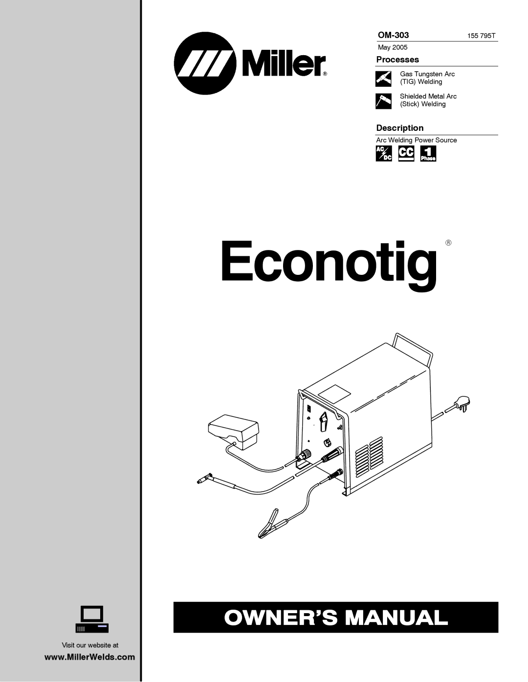
Description
Arc Welding Power Source
Visit our website at
www.MillerWelds.com
May 2005
Gas Tungsten Arc
(TIG) Welding
Shielded Metal Arc
(Stick) Welding
Arc Welding Power Source