9-3. Correct Installation
Weld Zone
350 ft
(15 m)
7
50ft
(15 m)
5
61
8 ![]()
![]()
![]()
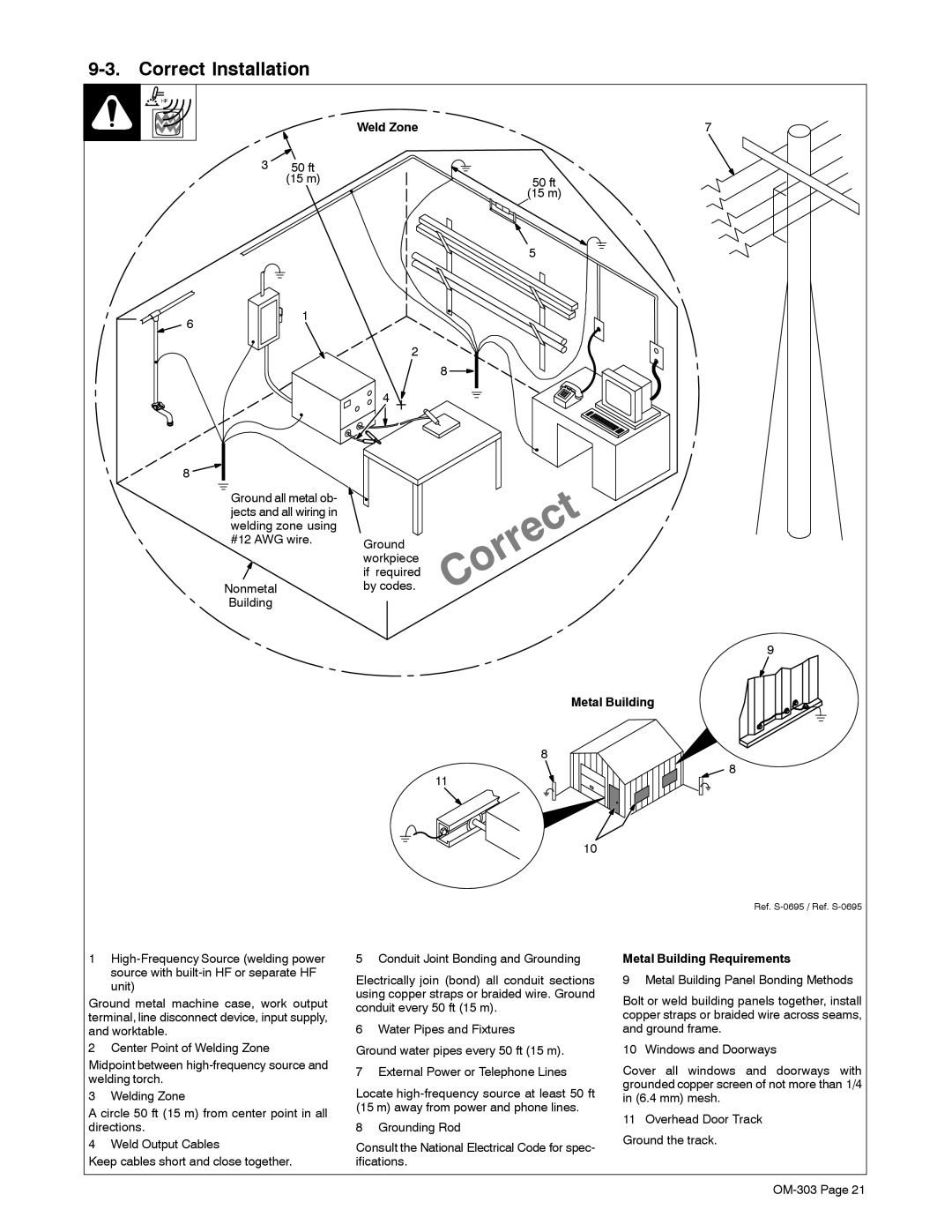
Ground all metal ob- jects and all wiring in welding zone using #12 AWG wire.
Nonmetal
Building
2
8
4
Ground workpiece if required by codes.
11
9
Metal Building
8
8
10
Ref.
1 | 5 Conduit Joint Bonding and Grounding | Metal Building Requirements | ||
| source with | Electrically join (bond) all conduit sections | 9 Metal Building Panel Bonding Methods | |
| unit) | |||
| using copper straps or braided wire. Ground | Bolt or weld building panels together, install | ||
Ground metal machine case, work output | ||||
conduit every 50 ft (15 m). | ||||
terminal, line disconnect device, input supply, | copper straps or braided wire across seams, | |||
| ||||
and worktable. | 6 Water Pipes and Fixtures | and ground frame. | ||
2 Center Point of Welding Zone | Ground water pipes every 50 ft (15 m). | 10 Windows and Doorways | ||
Midpoint between | 7 External Power or Telephone Lines | Cover all windows and doorways with | ||
welding torch. | ||||
Locate | grounded copper screen of not more than 1/4 | |||
3 | Welding Zone | |||
in (6.4 mm) mesh. | ||||
A circle 50 ft (15 m) from center point in all | (15 m) away from power and phone lines. | 11 Overhead Door Track | ||
directions. | 8 Grounding Rod | |||
Ground the track. | ||||
4 | Weld Output Cables | Consult the National Electrical Code for spec- | ||
| ||||
Keep cables short and close together. | ifications. |
| ||