GAIN TRIMLEFT
30
30
THE GUTS |
|
AC MAINS | VOLTAGE |
| GAIN TRIMRIGHT |
| 30 |
| 30 |
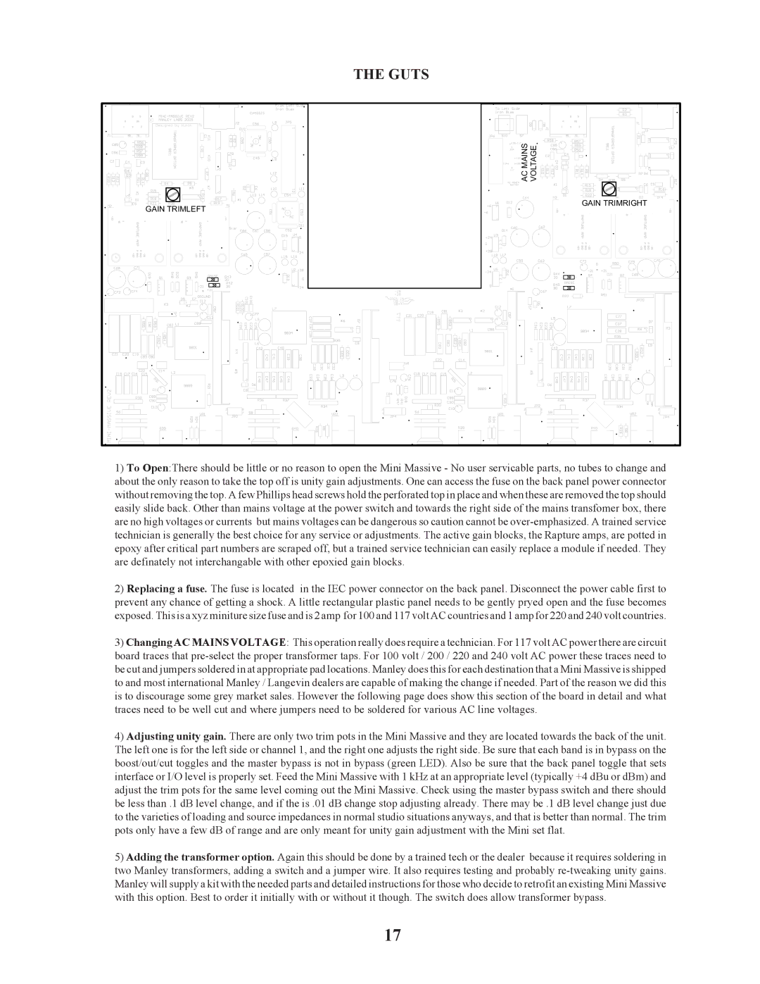
1)To Open:There should be little or no reason to open the Mini Massive - No user servicable parts, no tubes to change and about the only reason to take the top off is unity gain adjustments. One can access the fuse on the back panel power connector without removing the top. A few Phillips head screws hold the perforated top in place and when these are removed the top should easily slide back. Other than mains voltage at the power switch and towards the right side of the mains transfomer box, there are no high voltages or currents but mains voltages can be dangerous so caution cannot be
2)Replacing a fuse. The fuse is located in the IEC power connector on the back panel. Disconnect the power cable first to prevent any chance of getting a shock. A little rectangular plastic panel needs to be gently pryed open and the fuse becomes exposed. This is a xyz miniture size fuse and is 2 amp for 100 and 117 volt AC countries and 1 amp for 220 and 240 volt countries.
3)Changing AC MAINS VOLTAGE: This operation really does require a technician. For 117 volt AC power there are circuit board traces that
4)Adjusting unity gain. There are only two trim pots in the Mini Massive and they are located towards the back of the unit. The left one is for the left side or channel 1, and the right one adjusts the right side. Be sure that each band is in bypass on the boost/out/cut toggles and the master bypass is not in bypass (green LED). Also be sure that the back panel toggle that sets interface or I/O level is properly set. Feed the Mini Massive with 1 kHz at an appropriate level (typically +4 dBu or dBm) and adjust the trim pots for the same level coming out the Mini Massive. Check using the master bypass switch and there should be less than .1 dB level change, and if the is .01 dB change stop adjusting already. There may be .1 dB level change just due to the varieties of loading and source impedances in normal studio situations anyways, and that is better than normal. The trim pots only have a few dB of range and are only meant for unity gain adjustment with the Mini set flat.
5)Adding the transformer option. Again this should be done by a trained tech or the dealer because it requires soldering in two Manley transformers, adding a switch and a jumper wire. It also requires testing and probably
17