EXT10 Assembly, con’t
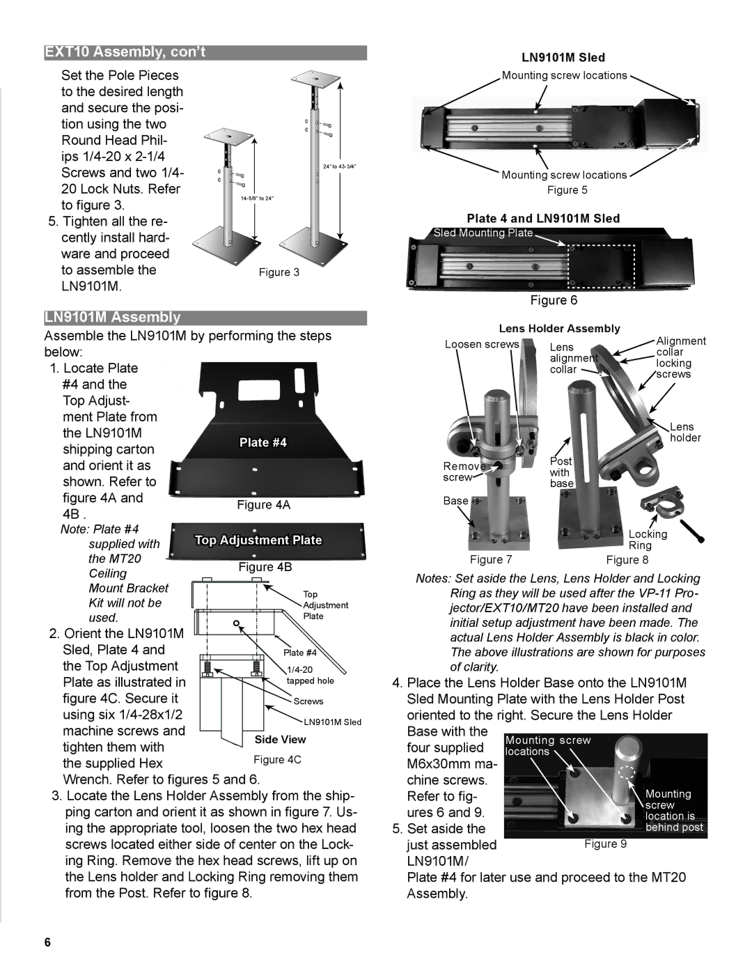
Set the Pole Pieces to the desired length and secure the posi- tion using the two Round Head Phil- ips
5. Tighten all the re- cently install hard- ware and proceed to assemble the LN9101M.
24” to
Figure 3
LN9101M Sled
Mounting screw locations
Mounting screw locations ![]()
Figure 5
Plate 4 and LN9101M Sled
Sled Mounting Plate
Figure 6
LN9101M Assembly
Assemble the LN9101M by performing the steps below:
1.Locate Plate #4 and the Top Adjust- ment Plate from
the LN9101M | Plate #4 | |
shipping carton | ||
| ||
and orient it as |
| |
shown. Refer to |
| |
figure 4A and | Figure 4A | |
4B . | ||
| ||
Note: Plate #4 | Top Adjustment Plate | |
supplied with | ||
the MT20 | Figure 4B | |
Ceiling | ||
| ||
Mount Bracket | Top | |
Kit will not be | ||
Adjustment | ||
used. | Plate | |
2. Orient the LN9101M |
| |
Sled, Plate 4 and | Plate #4 | |
the Top Adjustment | ||
Plate as illustrated in | tapped hole | |
figure 4C. Secure it | Screws | |
using six | LN9101M Sled | |
machine screws and | ||
Side View | ||
tighten them with | ||
Figure 4C | ||
the supplied Hex |
Wrench. Refer to figures 5 and 6.
3.Locate the Lens Holder Assembly from the ship- ping carton and orient it as shown in figure 7. Us- ing the appropriate tool, loosen the two hex head screws located either side of center on the Lock- ing Ring. Remove the hex head screws, lift up on the Lens holder and Locking Ring removing them from the Post. Refer to figure 8.
Lens Holder Assembly | Alignment | |
Loosen screws | Lens | |
| alignment | collar |
| locking | |
| collar | |
| screws | |
|
| |
|
| Lens |
|
| holder |
RemovePost
screwwith base
Base
| Locking |
Figure 7 | Ring |
Figure 8 |
Notes: Set aside the Lens, Lens Holder and Locking Ring as they will be used after the
4.Place the Lens Holder Base onto the LN9101M Sled Mounting Plate with the Lens Holder Post
oriented to the right. Secure the Lens Holder Base with the
four supplied M6x30mm ma- chine screws. Refer to fig-
ures 6 and 9. 5. Set aside the
just assembled LN9101M/
Plate #4 for later use and proceed to the MT20 Assembly.
6
