MT20 Assembly
Assemble the MT20 by performing the steps below, | |
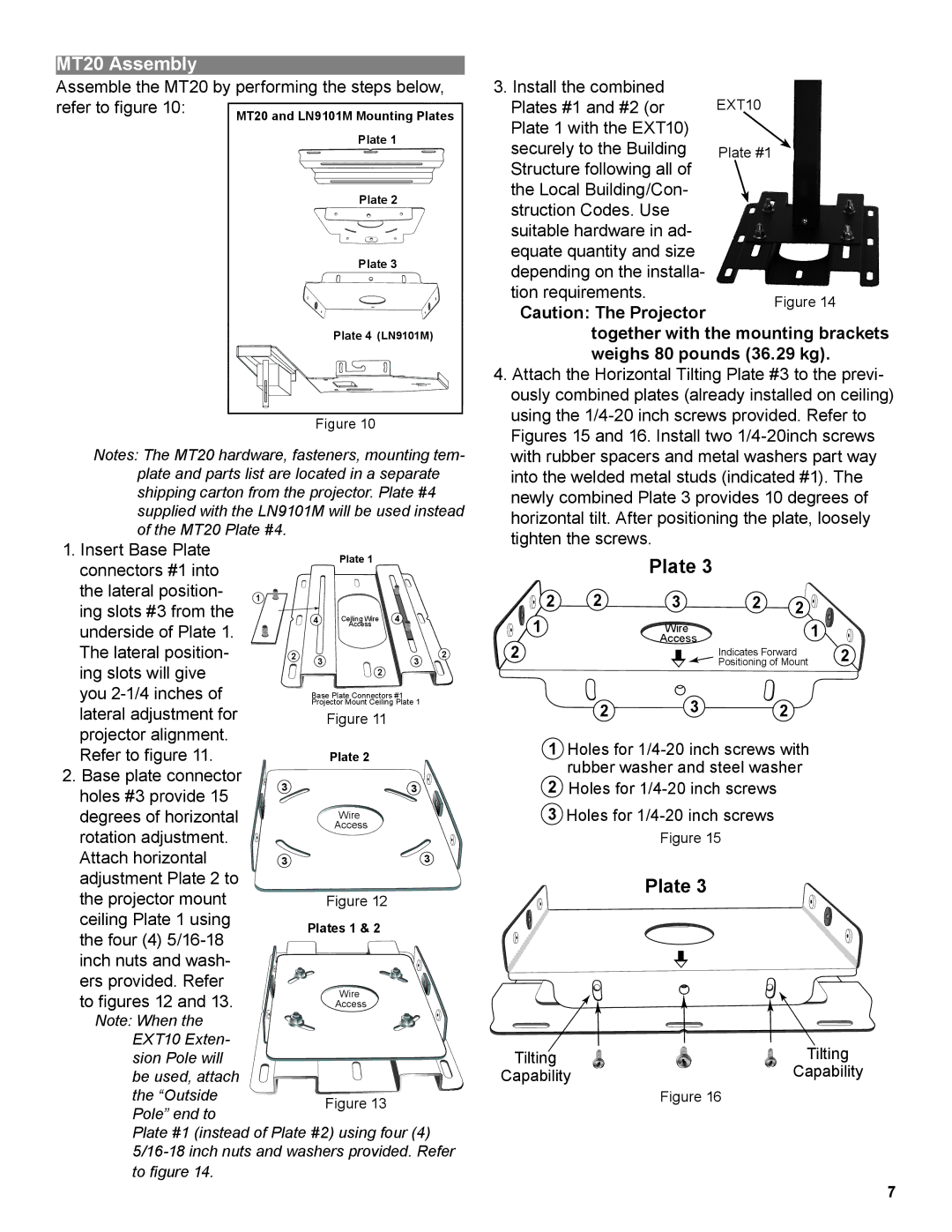
refer to figure 10: | MT20 and LN9101M Mounting Plates |
| |
| Plate 1 |
| Plate 2 |
| Plate 3 |
| Plate 4 (LN9101M) |
Figure 10
Notes: The MT20 hardware, fasteners, mounting tem- plate and parts list are located in a separate shipping carton from the projector. Plate #4 supplied with the LN9101M will be used instead of the MT20 Plate #4.
1. Insert Base Plate |
|
| Plate 1 |
|
|
connectors #1 into |
|
|
|
| |
|
|
|
|
| |
the lateral position- | 1 |
|
|
|
|
ing slots #3 from the |
| 4 | Ceiling Wire | 4 |
|
underside of Plate 1. |
|
| Access |
|
|
|
|
|
|
| |
The lateral position- | 2 | 3 |
| 3 | 2 |
ing slots will give |
| 2 |
| ||
|
|
|
| ||
you |
| Projector Mount Ceiling Plate 1 |
| ||
|
| Base Plate Connectors #1 |
| ||
lateral adjustment for |
| Figure 11 | |
projector alignment. |
|
| |
Refer to figure 11. |
| Plate 2 | |
2. Base plate connector | 3 | 3 | |
holes #3 provide 15 | |||
|
| ||
degrees of horizontal |
| Wire | |
rotation adjustment. |
| Access | |
|
| ||
Attach horizontal | 3 | 3 | |
adjustment Plate 2 to |
|
| |
the projector mount |
| Figure 12 | |
ceiling Plate 1 using |
| Plates 1 & 2 | |
the four (4) |
| ||
|
| ||
inch nuts and wash- |
|
| |
ers provided. Refer |
| Wire | |
to figures 12 and 13. |
| ||
| Access | ||
Note: When the |
|
| |
EXT10 Exten- |
|
| |
sion Pole will |
|
| |
be used, attach |
|
| |
the “Outside |
| Figure 13 | |
Pole” end to |
| ||
|
| ||
Plate #1 (instead of Plate #2) using four (4) | |||
to figure 14. |
|
| |
3. Install the combined | EXT10 | |
Plates #1 and #2 (or | ||
Plate 1 with the EXT10) |
| |
securely to the Building | Plate #1 | |
Structure following all of |
| |
the Local Building/Con- |
| |
struction Codes. Use |
| |
suitable hardware in ad- |
| |
equate quantity and size |
| |
depending on the installa- |
| |
tion requirements. | Figure 14 | |
Caution: The Projector | ||
|
together with the mounting brackets weighs 80 pounds (36.29 kg).
4.Attach the Horizontal Tilting Plate #3 to the previ- ously combined plates (already installed on ceiling) using the
Plate 3
2 | 2 | 3 | 2 | 2 |
|
1 |
| Wire |
|
| 1 |
2 |
| Access |
|
| |
|
| Indicates Forward | 2 | ||
|
| Positioning of Mount | |||
2 3 2
1Holes for
2Holes for
3Holes for
Figure 15
Plate 3
Tilting | Tilting |
Capability | Capability |
| Figure 16 |
7