Marantz DR-6000, MAR770, MAR775 Test instructions, Supply voltages, Clock signal, Control signals

Models: MAR770 MAR775 DR-6000

1 45
Download 45 pages 40.48 Kb
Page 19
Image 19

8.1.2 Test instructions

Grid lines


Level and timing of all grid lines, G1-->G15, can be checked

Supply voltages

either at the FTD itself or at the display controller. Grid lines

The display board receives several voltages via connector

G13, G14 and G15 each have an extra current amplifier in line

JY01.

: QY02 for G13, QY03 for G14 and QY04 for G15. A typical

• VFTD : -35V ±5% measured at pin 2 of conn. JY01.

grid line signal shows in the oscillogram below.

VDC1-VDC2 : 3V8 ±10% measured between pin 1 and 3 of


conn. 1119.


PM3392A


+5V

+5V: ±5% measured at pin 10 of conn. JY01


Voltages VFTD, VDC1 and VDC2 are produced in the power


supply unit and sent to the display board via the CDR main

+4V


board. The +5V voltage is produced on the CDR main board as

0V


D5V.


Clock signal


As clock driver for the display controller, a resonator of 8 MHz


(XY01) is used. The signal can be measured at pins 8 and 9 of


the display controller : 8 MHz ±5%.


Control signals


-38V


RESET


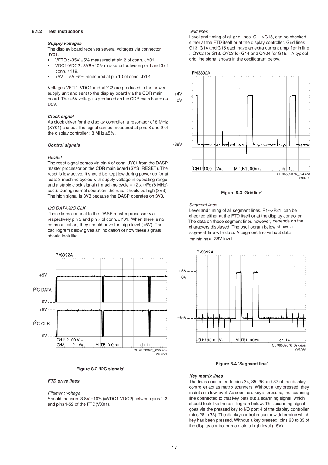
The reset signal comes via pin 4 of conn. JY01 from the DASP


master processor on the CDR main board (SYS_RESET). The

CH1! 10.0

V=

M TB1. 00ms

ch 1+

reset is low active. It should be kept low during power up for at


CL 96532076_024.eps

least 3 machine cycles with supply voltage in operating range


290799


and a stable clock signal (1 machine cycle = 12 x 1/Fc (8 MHz)


sec.). During normal operation, the reset should be high (3V3).


Figure 8-3 ‘Gridline’


The high signal is 3V3 because the DASP operates on 3V3.


I2C DATA/I2C CLK


Segment lines


Level and timing of all segment lines, P1-->P21, can be

These lines connect to the DASP master processor via

checked either at the FTD itself or at the display controller.

respectively pin 5 and pin 7 of conn. JY01. When there is no

The data on these segment lines however, depends on the

communication, they should have the high level (+5V). The

characters displayed. The oscillogram below shows a

oscillogram below gives an indication of how these signals

segment line with data. A segment line without data

should look like.


maintains a -38V level.


PM33 92A


PM33 92A


+5V


+5V


0V


I2C DATA


0V


+5V


I2C CLK


-35V


0V

CH1! 2. 00 V =


CH1! 10 .0

V=

M TB1. 00ms

ch 1+


CH2

2

V=

M TB10.0m s

ch 1+


CL 96532076_027.eps


CL 96532076_025.eps


290799


290799


Figure 8-2 ‘I2C signals’


Figure 8-4 ‘Segment line’


FTD drive lines

Filament voltage

Should measure 3.8V ±10% (=VDC1-VDC2) between pins 1-3 and pins 1-52 of the FTD(VX01).

Key matrix lines

The lines connected to pins 34, 35, 36 and 37 of the display controller act as matrix scanners. Without a key pressed, they maintain a low level. As soon as a key is pressed, the scanning line connected to that key puts out a scanning signal, which should look like the oscillogram below. This scanning signal goes via the pressed key to I/O port 4 of the display controller (pins 28 to 33). The display controller can now determine which key has been pressed. Without a key pressed, pins 28 to 33 of the display controller maintain a high level (+5V).

17

Page 19
Image 19
Marantz DR-6000 Test instructions, Supply voltages, Clock signal, Control signals, FTD drive lines, Key matrix lines

MAR770, MAR775, DR-6000 specifications

The Marantz DR-6050 and DR-6000 are revered components in the world of high-fidelity audio systems, reflecting the brand's long-standing commitment to quality and performance. These models have gained popularity among audiophiles for their comprehensive features and advanced technologies, which cater to both casual listeners and serious music enthusiasts.

The Marantz DR-6050 is a CD recorder and player that stands out with its dual functionality. It allows users to enjoy CDs while also having the capability to record directly from various sources, including analog inputs and digital connections. This functionality is essential for those who wish to preserve their vinyl records, cassettes, or other audio formats onto CD. The machine supports CD-R and CD-RW media, providing flexibility for repeated use and recording.

One of the standout technologies in the DR-6050 is its high-quality Digital-to-Analog Converter (DAC), which significantly enhances sound performance by converting digital signals to analog with incredible accuracy. This contributes to the unit's ability to reproduce audio with rich detail and clarity. Additionally, the recorder is equipped with a Microprocessor that ensures precise recording levels and optimizes the quality of the output.

On the other hand, the Marantz DR-6000 offers similar capabilities but with an emphasis on simplicity and ease of use. Designed for users who appreciate an intuitive interface, it features straightforward controls and an ergonomic design. The DR-6000 supports multiple recording formats, including standard audio CDs, making it versatile for various playback systems.

Both models are built with high-grade components that promise longevity and reliability. They feature robust construction, ensuring minimal vibration and interference to enhance playback quality. Integrated analog and digital inputs allow for diverse connectivity options, which is crucial for users with elaborate audio setups.

In terms of audio performance, both the DR-6050 and DR-6000 exhibit impressive frequency response and low distortion levels, characteristics that are vital for a satisfying listening experience. The devices also include features like playback speed control and disc finalization options, providing the user with complete control over their audio sessions.

The Marantz DR-6050 and DR-6000 are ultimate companions for those who appreciate high-quality sound and need versatile recording solutions. With their blend of advanced technologies, clear audio output, and user-friendly designs, they remain solid choices for anyone looking to enhance their audio collection and experience.