®
|
|
| |
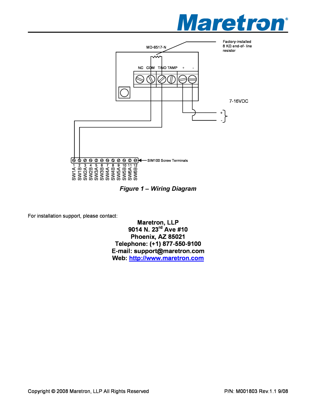
NC | COM T/NO TAMP | + | - |
![]() SIM100 Screw Terminals
SIM100 Screw Terminals
1 | 2 | 3 | 4 | 5 | 6 | 7 | 8 | 9 | 10 11 12 |
SW1A | SW1B | SW2A | SW2B | SW3A | SW3B | SW4A | SW4B | SW5A | SW5B SW6A SW6B |
Figure 1 – Wiring Diagram
For installation support, please contact:
Maretron, LLP
9014 N. 23rd Ave #10
Phoenix, AZ 85021
Telephone: (+1)
Copyright © 2008 Maretron, LLP All Rights Reserved
8KΩ
+
-
P/N: M001803 Rev.1.1 9/08
