Mark Levinson No. 53 Eliminating Dead Bands, Optimizing The Layout, It’S Your Turn To Listen

Models: No. 53

1 8
Download 8 pages 875 b
Page 5
Image 5
ELIMINATING DEAD BANDS

2MHz, delivering two major sonic advantages. First, it pushes the fundamental switching noise and associated harmonics so far above the limit of human hearing that they have no direct effect on sound quality. (In fact, most audio testing devices can’t even measure such frequencies.) Second, it allows for easier removal of switching noise from the signal with much gentler notch filters, which have no negative effect on the crucial audio band. The result is frequency response that is ruler-flat across the entire audio spectrum, dipping only a few dB at 100kHz. That’s impressive performance for any power amplifier. For a switching power amplifier, it’s nothing short of remarkable.

ELIMINATING DEAD BANDS

The other technical challenge for switching power amplifiers are dead bands – silent gaps in audio output created when the output devices driving the positive half of the signal and outputs driving the negative half are both turned off. This occurs every time the audio waveform crosses from positive amplitude to negative amplitude, or back again (about forty thousand times per second for a 20kHz audio signal). Because even the best output devices cannot switch on and off instantaneously, a signal gap is created between each half of every wave- form. Large gaps are highly detrimental to the audio signal, but even the tiniest gaps have a negative impact on sound quality – listeners will perceive that something isn’t right.

Dead bands can be minimized by keeping both sets of outputs off for as short a time as technically possible. But doing that increases the possibility that opposing output devices may come on at the same time – doubling the voltage they draw – which could easily damage or destroy them. Engineers are forced to arrive at a middle ground between sound quality and reliability when designing switching power amplifiers.

Mark Levinson engineers saw this as unacceptable and instead developed a patented technology for the No53 that permits both sets of output devices to be on simultaneously for short periods of time. Dead bands are completely eliminated, without in any way compromising the life expectancy of the output devices.

OPTIMIZING THE LAYOUT

The primary function of any Mark Levinson Reference product is to reproduce sound at the purest level possible. With power amplifiers, the challenge is to amplify the incoming audio signal without distorting it and to effortlessly drive a wide range of loudspeaker impedances at any volume level with the forcefulness and grace that Reference-quality sound reproduction demands.

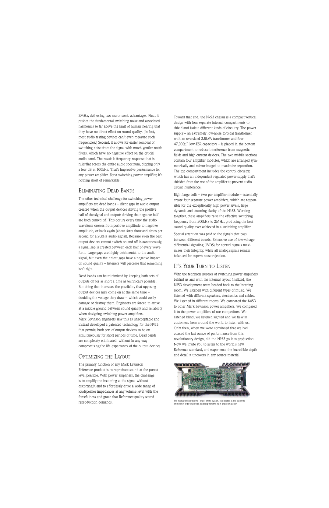
Toward that end, the No53 chassis is a compact vertical design with four separate internal compartments to shield and isolate different kinds of circuitry. The power supply – an extremely low-noise toroidal transformer with an oversized 2.8kVA transformer and four 47,000µF low-ESR capacitors – is placed in the bottom compartment to reduce interference from magnetic fields and high-current devices. The two middle sections contain four amplifier modules, which are arranged sym- metrically and mirror-imaged to maximize separation. The top compartment includes the control circuitry, which has an independent regulated power supply that’s shielded from the rest of the amplifier to prevent audio- circuit interference.

Eight large coils – two per amplifier module – essentially create four separate power amplifiers, which are respon- sible for the exceptionally high power levels, large dynamic and stunning clarity of the No53. Working together, these amplifiers raise the effective switching frequency from 500kHz to 2MHz, producing the best sound quality ever achieved in a switching amplifier.

Special attention was paid to the signals that pass between different boards. Extensive use of low-voltage- differential signaling (LVDS) for control signals maxi- mizes their integrity, while all analog signals remain balanced for superb noise rejection.

ITS YOUR TURN TO LISTEN

With the technical hurdles of switching power amplifiers behind us and with the internal layout finalized, the No53 development team headed back to the listening room. We listened with different types of music. We listened with different speakers, electronics and cables. We listened in different rooms. We compared the No53 to other Mark Levinson power amplifiers. We compared it to the power amplifiers of our competitors. We listened blind, we listened sighted and we flew in customers from around the world to listen with us. Only then, when we were convinced that we had coaxed the last ounce of performance from this revolutionary design, did the No53 go into production. Now we invite you to listen to the world’s new Reference standard, and experience the incredible depth and detail it uncovers in any source material.

The modulator board is the “brain” of the system. It is located at the top of the amplifier in order to provide shielding from the main amplifier section.

Page 5
Image 5
Mark Levinson No. 53 manual Eliminating Dead Bands, Optimizing The Layout, It’S Your Turn To Listen