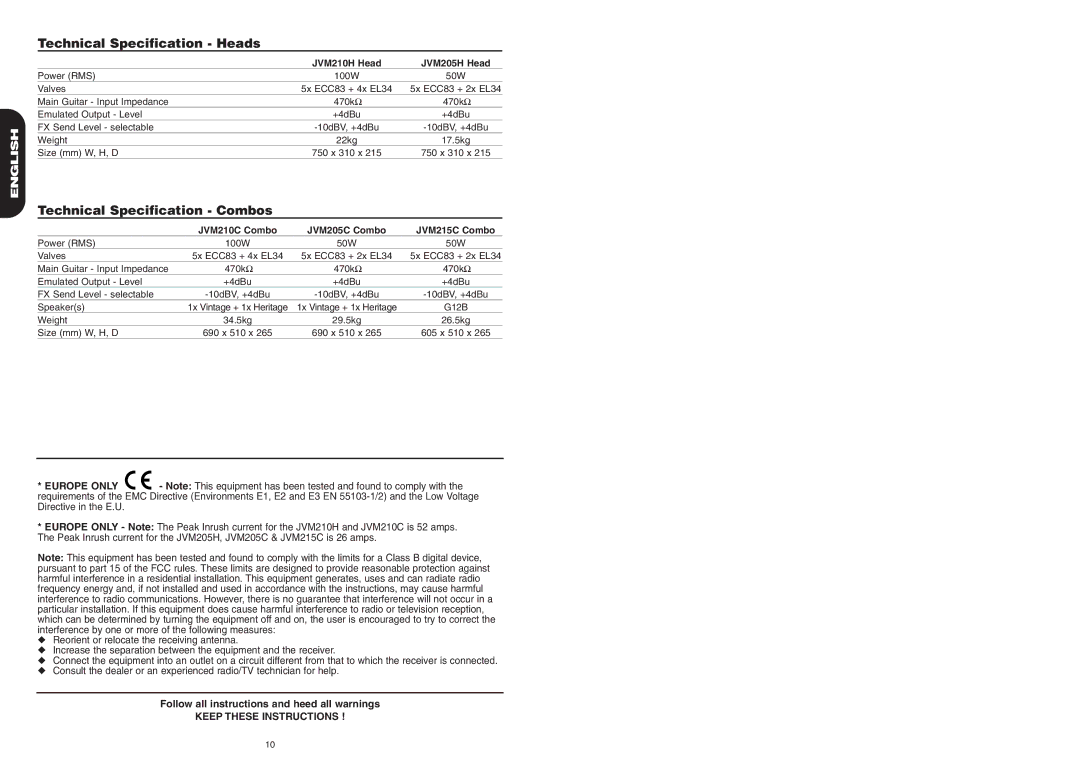
Technical Specification - Heads
|
|
| JVM210H Head | JVM205H Head |
| Power (RMS) |
| 100W | 50W |
| Valves |
| 5x ECC83 + 4x EL34 | 5x ECC83 + 2x EL34 |
| Main Guitar - Input Impedance |
| 470kΩ | 470kΩ |
| Emulated Output - Level |
| +4dBu | +4dBu |
ENGLISH | FX Send Level - selectable |
| ||
Weight |
| 22kg | 17.5kg | |
|
| |||
| Size (mm) W, H, D |
| 750 x 310 x 215 | 750 x 310 x 215 |
| Technical Specification - Combos |
|
| |
|
| JVM210C Combo | JVM205C Combo | JVM215C Combo |
| Power (RMS) | 100W | 50W | 50W |
| Valves | 5x ECC83 + 4x EL34 | 5x ECC83 + 2x EL34 | 5x ECC83 + 2x EL34 |
| Main Guitar - Input Impedance | 470kΩ | 470kΩ | 470kΩ |
| Emulated Output - Level | +4dBu | +4dBu | +4dBu |
| FX Send Level - selectable | |||
| Speaker(s) | 1x Vintage + 1x Heritage | 1x Vintage + 1x Heritage | G12B |
| Weight | 34.5kg | 29.5kg | 26.5kg |
| Size (mm) W, H, D | 690 x 510 x 265 | 690 x 510 x 265 | 605 x 510 x 265 |
* EUROPE ONLY ![]()
![]() - Note: This equipment has been tested and found to comply with the requirements of the EMC Directive (Environments E1, E2 and E3 EN
- Note: This equipment has been tested and found to comply with the requirements of the EMC Directive (Environments E1, E2 and E3 EN
*EUROPE ONLY - Note: The Peak Inrush current for the JVM210H and JVM210C is 52 amps. The Peak Inrush current for the JVM205H, JVM205C & JVM215C is 26 amps.
Note: This equipment has been tested and found to comply with the limits for a Class B digital device, pursuant to part 15 of the FCC rules. These limits are designed to provide reasonable protection against harmful interference in a residential installation. This equipment generates, uses and can radiate radio frequency energy and, if not installed and used in accordance with the instructions, may cause harmful interference to radio communications. However, there is no guarantee that interference will not occur in a particular installation. If this equipment does cause harmful interference to radio or television reception, which can be determined by turning the equipment off and on, the user is encouraged to try to correct the
◆by one or more of the following measures:
◆Reorient or relocate the receiving antenna.
◆Increase the separation between the equipment and the receiver.
◆Connect the equipment into an outlet on a circuit different from that to which the receiver is connected. Consult the dealer or an experienced radio/TV technician for help.interference
Follow all instructions and heed all warnings
KEEP THESE INSTRUCTIONS !
10
