REMOTE SUBMENU
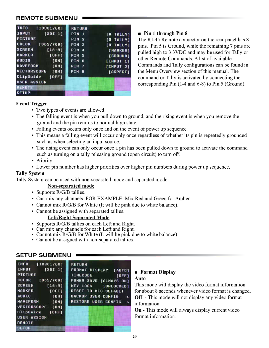
■ Pin 1 through Pin 8
The
Event Trigger
•Two types of events are allowed.
•The falling event is when you pull down to ground, and the rising event is when you remove the ground and the pin returns to normal high state.
•Falling events occurs only once and on the event of power up sequence.
•This means a falling event will occur only once regardless of whether its pin is repeatedly grounded such as when selecting an input source.
•The rising event can only occur once a pin has been pulled down to ground to activate the command such as turning on a tally releasing ground (open circuit) to turn off.
•Priority
•Lower pin number has higher priorities over higher pin numbers during power up sequence.
Tally System
Tally System can be used with
Non-separated mode
•Supports R/G/B tallies.
•Can mix any channels. FOR EXAMPLE: Mix Red and Green for Amber.
•Cannot mix R/G/B for White (It will be pink due to white balance).
•Cannot be assigned with separated tallies.
Left/Right Separated Mode
•Supports R/G/B tallies on each Left and Right.
•Can mix any channels for each Left and Right.
•Cannot mix R/G/B for White (It will be pink due to white balance).
•Cannot be assigned with
SETUP SUBMENU
■ Format Display
Auto
This mode will display the video format information for about 8 seconds whenever video format is changed. Off - This mode will not display any video format information.
On - This mode will always display current video format information.
20