Rear Panel Features
1
4
3
2
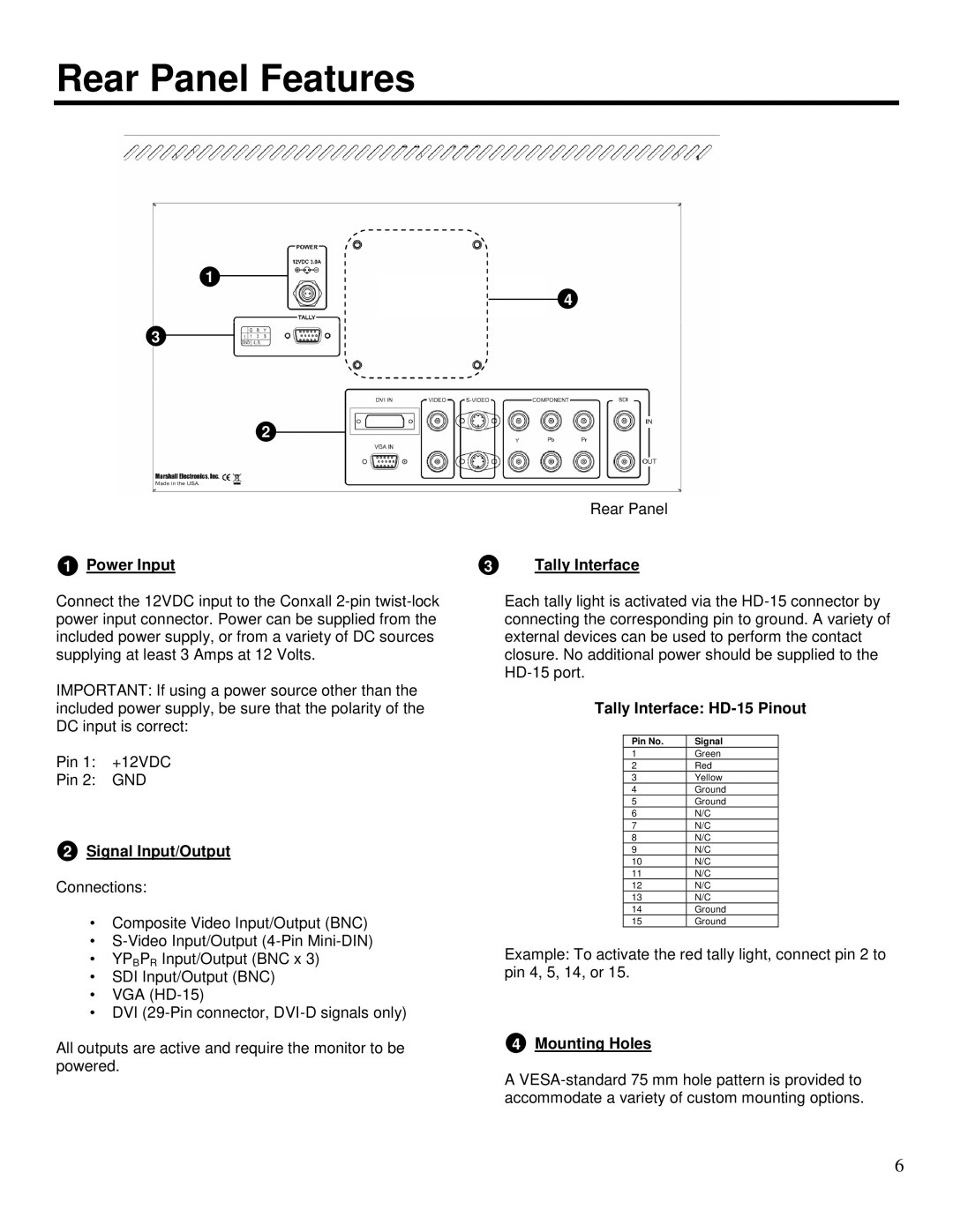
Rear Panel
1 Power Input | 3 | Tally Interface |
Connect the 12VDC input to the Conxall
IMPORTANT: If using a power source other than the included power supply, be sure that the polarity of the DC input is correct:
Pin 1: +12VDC
Pin 2: GND
2Signal Input/Output
Connections:
•Composite Video Input/Output (BNC)
•
•YPBPR Input/Output (BNC x 3)
•SDI Input/Output (BNC)
•VGA
•DVI
All outputs are active and require the monitor to be powered.
Each tally light is activated via the
Tally Interface: HD-15 Pinout
Pin No. | Signal |
1 | Green |
2 | Red |
3 | Yellow |
4 | Ground |
5 | Ground |
6 | N/C |
7 | N/C |
8 | N/C |
9 | N/C |
10 | N/C |
11 | N/C |
12 | N/C |
13 | N/C |
14 | Ground |
15 | Ground |
Example: To activate the red tally light, connect pin 2 to pin 4, 5, 14, or 15.
4Mounting Holes
A
6