Rear Panel Features
The
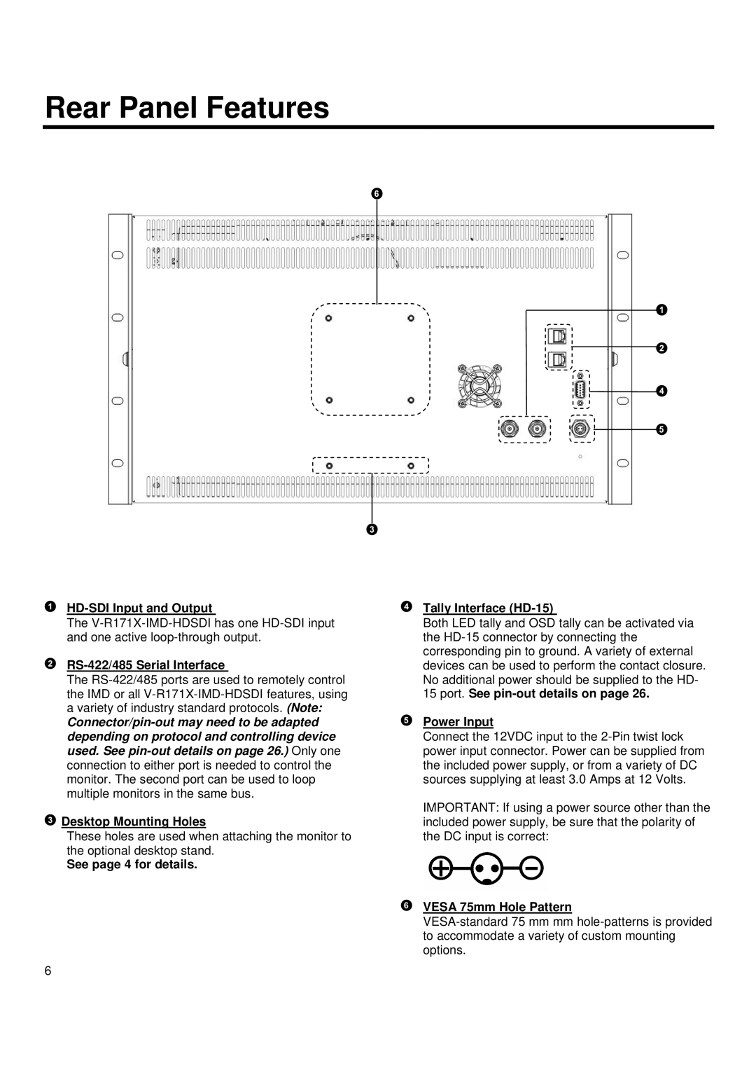
RS-422/485 Serial Interface
The
![]() Desktop Mounting Holes
Desktop Mounting Holes
These holes are used when attaching the monitor to the optional desktop stand.
See page 4 for details.
6
Tally Interface (HD-15)
Both LED tally and OSD tally can be activated via the
Power Input
Connect the 12VDC input to the
IMPORTANT: If using a power source other than the included power supply, be sure that the polarity of the DC input is correct: