IIIx Operation
Crossover Settings
Before you do any formal listening, you must set a pair of switches in the crossover. However, if you are using identical amplifiers (i.e. same make and model) for the high and
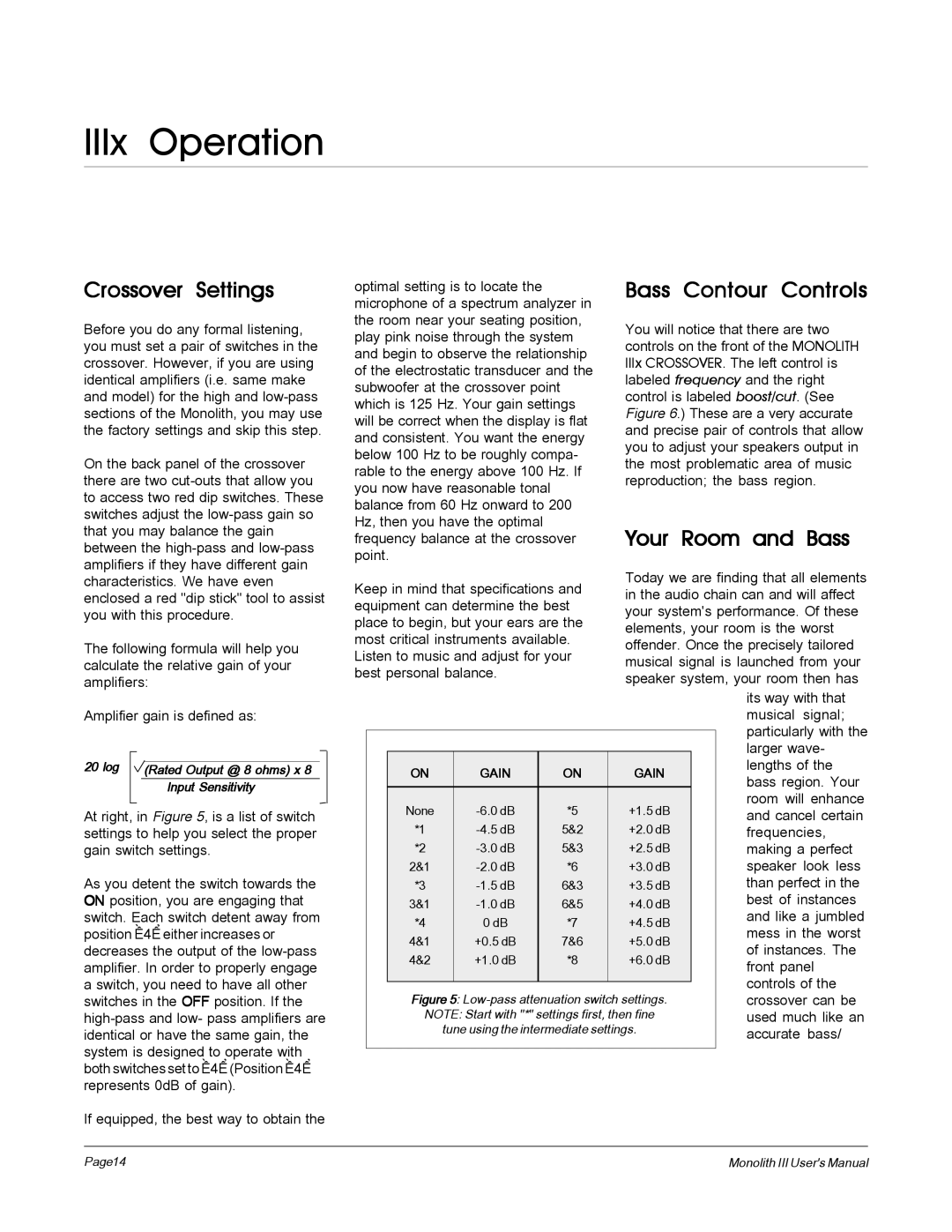
On the back panel of the crossover there are two
The following formula will help you calculate the relative gain of your amplifiers:
optimal setting is to locate the microphone of a spectrum analyzer in the room near your seating position, play pink noise through the system and begin to observe the relationship of the electrostatic transducer and the subwoofer at the crossover point which is 125 Hz. Your gain settings will be correct when the display is flat and consistent. You want the energy below 100 Hz to be roughly compa- rable to the energy above 100 Hz. If you now have reasonable tonal balance from 60 Hz onward to 200 Hz, then you have the optimal frequency balance at the crossover point.
Keep in mind that specifications and equipment can determine the best place to begin, but your ears are the most critical instruments available. Listen to music and adjust for your best personal balance.
Bass Contour Controls
You will notice that there are two controls on the front of the MONOLITH IIIx CROSSOVER. The left control is labeled frequency and the right control is labeled boost/cut. (See Figure 6.) These are a very accurate and precise pair of controls that allow you to adjust your speakers output in the most problematic area of music reproduction; the bass region.
Your Room and Bass
Today we are finding that all elements in the audio chain can and will affect your system's performance. Of these elements, your room is the worst offender. Once the precisely tailored musical signal is launched from your speaker system, your room then has
Amplifier gain is defined as:
20 log |
|
|
(Rated Output @ 8 ohms) x 8 | ||
|
| Input Sensitivity |
|
|
|
At right, in Figure 5, is a list of switch settings to help you select the proper gain switch settings.
As you detent the switch towards the ON position, you are engaging that switch. Each switch detent away from position “4” either increases or decreases the output of the
If equipped, the best way to obtain the
|
|
|
|
|
|
| its way with that |
|
|
|
|
|
|
| musical signal; |
|
|
|
|
|
|
| particularly with the |
|
|
|
|
|
|
| |
|
|
|
|
|
|
| larger wave- |
| ON |
| GAIN | ON | GAIN |
| lengths of the |
|
|
| bass region. Your | ||||
|
|
|
|
|
|
| |
| None |
| *5 | +1.5 dB |
| room will enhance | |
|
|
| and cancel certain | ||||
| *1 |
| 5&2 | +2.0 dB |
| frequencies, | |
| *2 |
| 5&3 | +2.5 dB |
| making a perfect | |
| 2&1 |
| *6 | +3.0 dB |
| speaker look less | |
| *3 |
| 6&3 | +3.5 dB |
| than perfect in the | |
| 3&1 |
| 6&5 | +4.0 dB |
| best of instances | |
| *4 |
| 0 dB | *7 | +4.5 dB |
| and like a jumbled |
|
|
| mess in the worst | ||||
| 4&1 |
| +0.5 dB | 7&6 | +5.0 dB |
| |
|
|
| of instances. The | ||||
| 4&2 |
| +1.0 dB | *8 | +6.0 dB |
| |
|
|
| front panel | ||||
|
|
|
|
|
|
| |
|
|
|
|
|
|
| controls of the |
|
|
|
|
|
| ||
| Figure 5: |
| crossover can be | ||||
| NOTE: Start with "*" settings first, then fine |
| used much like an | ||||
|
| tune using the intermediate settings. |
| accurate bass/ | |||
|
|
|
|
|
|
|
|
Page14 | Monolith III User's Manual |
