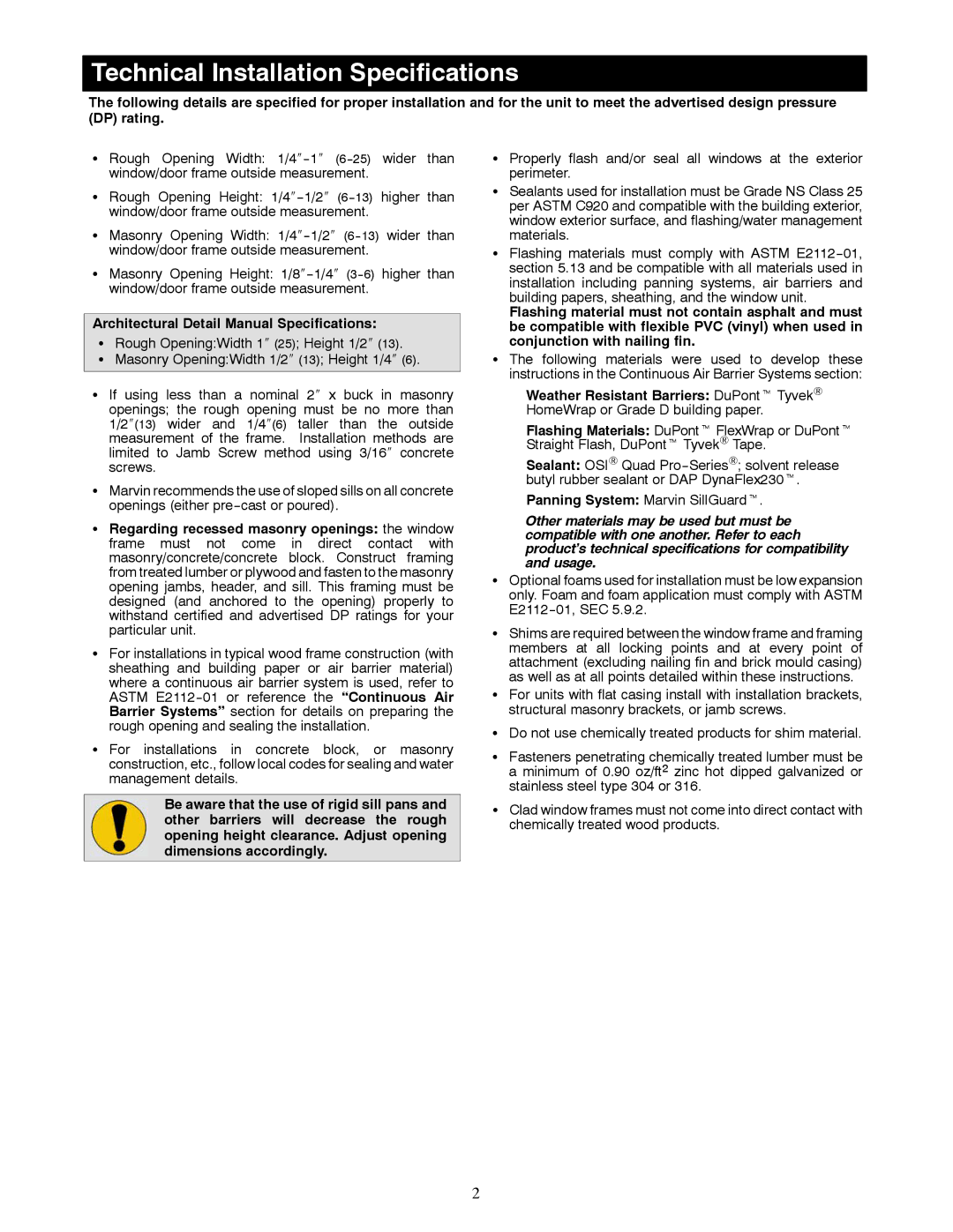
Window specifications
Marvin Windows is a renowned name in the window and door manufacturing industry, known for its commitment to quality, innovation, and energy efficiency. Established in 1912, Marvin has built a legacy of craftsmanship and performance that meets the diverse needs of homeowners, builders, and architects alike.One of the main features of Marvin Windows is their customizable design options. Customers can choose from a wide array of styles, shapes, colors, and finishes, allowing them to tailor their windows and doors to perfectly match their aesthetic preferences and architectural styles. Whether it's a traditional double-hung window or a modern sliding door, Marvin offers solutions that can enhance both the beauty and functionality of any property.
In terms of technology, Marvin Windows employs advanced energy-efficient technologies, such as Low-E glass coatings and gas fills, to reduce heat loss and gain. Low-E (low emissivity) glass minimizes the amount of ultraviolet and infrared light that can enter the home without compromising natural light. Furthermore, Marvin windows are often engineered with argon or krypton gas fills between the panes, which helps to improve thermal insulation and overall energy performance. This focus on energy efficiency not only contributes to reduced energy bills but also promotes sustainability in home design.
Marvin is also known for its durable materials. The company utilizes high-quality wood, fiberglass, and vinyl, ensuring each window and door can withstand the elements while providing longevity and performance. Their Ultrex fiberglass has a reputation for being nearly four times stronger than vinyl, making it resistant to warping, bowing, or cracking. This durability is complemented by a rigorous testing process that ensures their products can endure various weather conditions, making Marvin windows a reliable choice for any climate.
Another characteristic that sets Marvin apart is their commitment to sustainability. They strive to minimize their environmental impact by using responsibly sourced materials and implementing eco-friendly manufacturing processes. This dedication to sustainability reflects their philosophy of creating products that contribute positively to both their customers’ lives and the environment.
In summary, Marvin Windows combines customizable design, advanced energy-efficient technologies, durable materials, and a commitment to sustainability, making them a premier choice in the window and door market. Their products stand as a testament to quality craftsmanship and innovative solutions, catering to the evolving needs of modern homeowners and builders.

