OWNER’S MANUAL
ILLUSTRATED
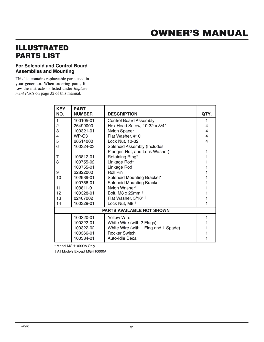
PARTS LIST
For Solenoid and Control Board
Assemblies and Mounting
This list contains replaceable parts used in your generator. When ordering parts, fol- low the instructions listed under Replace- ment Parts on page 32 of this manual.
KEY | PART |
|
|
|
NO. | NUMBER |
| DESCRIPTION | QTY. |
|
|
|
|
|
1 |
| Control Board Assembly | 1 | |
2 | 26499000 |
| Hex Head Screw, | 4 |
3 |
| Nylon Spacer | 4 | |
4 |
| Flat Washer, #10 | 4 | |
5 | 26514000 |
| Lock Nut, | 4 |
6 |
| Solenoid Assembly (Includes |
| |
|
|
| Plunger, Nut, and Lock Washer) | 1 |
7 |
| Retaining Ring* | 1 | |
8 |
| Linkage Rod* | 1 | |
|
| Linkage Rod | 1 | |
9 | 22822000 |
| Roll Pin | 1 |
10 |
| Solenoid Mounting Bracket* | 1 | |
|
| Solenoid Mounting Bracket | 1 | |
11 |
| Nylon Washer* | 1 | |
12 |
| Bolt, M8 x 25mm † | 1 | |
13 | 02407002 |
| Flat Washer, 5/16" † | 1 |
14 |
| Lock Nut, M8 † | 1 | |
|
| PARTS AVAILABLE NOT SHOWN |
| |
|
|
|
|
|
|
| Yellow Wire | 1 | |
|
| White Wire (with 2 Flags) | 1 | |
|
| White Wire (with 1 Flag and 1 Spade) | 1 | |
|
| Rocker Switch | 1 | |
|
| 1 | ||
|
|
|
|
|
* Model MGH10000A Only
† All Models Except MGH10000A
106813 | 31 |