MAXON SM-2000 MOBILE
DESCRIPTION OF CONTROLS
DESCRIPTION OF CONTROLS
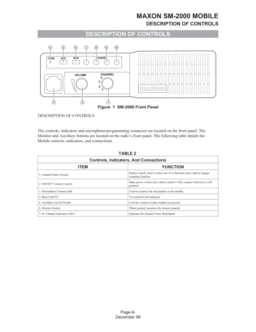
Figure 1 SM-2000 Front Panel
DESCRIPTION OF CONTROLS
The controls, indicators and microphone/programming connector are located on the front panel. The Monitor and Auxiliary buttons are located on the radio’s front panel. The following table details the Mobile controls, indicators, and connections.
|
| TABLE 2 | |
|
| Controls, Indicators, And Connections | |
|
|
|
|
| ITEM |
| FUNCTION |
|
|
|
|
1. | Channel Select Switch |
| Rotary switch, used to select one of 4 channels (max.) and to engage |
| scanning function | ||
|
|
| |
|
|
|
|
2. ON/OFF Volume Control |
| Main power switch and volume control. Fully counter clockwise is off | |
| position | ||
|
|
| |
|
|
|
|
3. | Microphone Connect Jack |
| Used to connect the microphone to the mobile |
|
|
|
|
4. | Busy/Call/TX |
| |
|
|
|
|
5. | Auxiliary (AUX) Switch |
| Used for control of after market accessories |
|
|
|
|
6. | Monitor Switch |
| When pushed, monitors the chosen channel |
|
|
| |
| Indicates the channel when illuminated | ||
|
|
|
|
December 98