AT INTERFACE DESCRIPTION

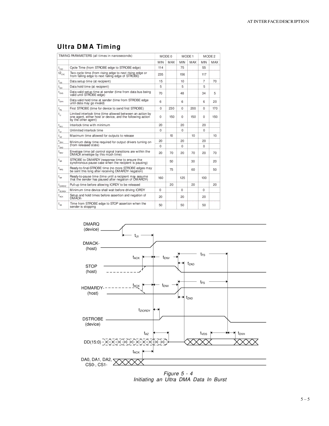
Ultra DMA Timing

TIMING PARAMETERS (all times in nanoseconds)

MODE 0

MODE 1

MODE 2


MIN

MAX

MIN

MAX

MIN

MAX


tCYC

Cycle Time (from STROBE edge to STROBE edge)

114


75


55


t2CYC

Two cycle time (from rising edge to next rising edge or

235


156


117


from falling edge to next falling edge of STROBE)


tDS

Data setup time (at recipient)

15


10


7

70

tDH

Data hold time (at recipient)

5


5


5


tDVS

Data valid setup time at sender (time from data bus being

70


48


34

5


valid until STROBE edge)


tDVH

Data valid hold time at sender (time from STROBE edge

6


6


6

20


until data may go invalid)


tFS

First STROBE (time for device to send first STROBE)

0

230

0

200

0

170

tLI

Limited interlock time (time allowed between an action by

0

150

0

150

0

150


one agent, either host or device, and the following action


by the other agent)


tMLI

Interlock time with minimum

20


20


20


tUI

Unlimited interlock time

0


0


0


tAZ

Maximum time allowed for outputs to release


10


10


10

tZAH

Minimum delay time required for output drivers turning on

20


20


20


tZAD

(from released state)

0


0


0


tENV

Envelope time (all control signal transitions are within the

20

70

20

70

20

70


DMACK envelope by this much time)


tSR

STROBE to DMARDY (response time to ensure the


50


30


20


synchronous pause case when the recipient is pausing)


tRFS

Ready-to-final-STROBE time (no more STROBE edges may


75


60


50


be sent this long after receiving DMARDY- negation)


tRP

Ready-to-pause time (time until a recipient may assume

160


125


100


that the sender has paused after negation of DMARDY-)


tIORDYZ

Pull-up time before allowing IORDY to be released


20


20


20

tZIORDY

Minimum time device shall wait before driving IORDY

0


0


0


tACK

Setup and hold times before assertion and negation of

20


20


20


DMACK-


tSS

Time from STROBE edge to STOP assertion when the

50


50


50


sender is stopping


DMARQ


(device)


tUI


DMACK-


(host)


tACK

tENV

STOP


(host)


tACK

tENV

HDMARDY-


(host)


tZIORDY


DSTROBE


(device)


tAZ


DD(15:0)


tACK


DA0, DA1, DA2,


CS0-, CS1-


tFS

tZAD


tFS


tZAD


tVDS

tDVH

Figure 5 - 4

Initiating an Ultra DMA Data In Burst

5 – 5

Page 36
Image 36
Maxtor 86480D6, 88400D8, 84320D4, 83240D3, 82160D2 specifications Ultra DMA Timing, Initiating an Ultra DMA Data In Burst

82160D2, 84320D4, 2160, 83240D3, 86480D6 specifications

Maxtor, known for its innovative storage solutions, produced several pivotal hard drive models during the late 1990s and early 2000s, namely the Maxtor 88400D8, 86480D6, 83240D3, 2160, and 84320D4. Each of these drives showcased unique features and technologies that catered to various computing needs.

The Maxtor 88400D8 stood out with its impressive storage capacity of 8.4 GB, which was considerable at the time. It employed the IDE interface, ensuring broad compatibility with most personal computers. The drive utilized a 5400 RPM spindle speed, optimizing data transfer rates for everyday applications. With a 2 MB cache, it facilitated smoother data retrieval, making it a reliable choice for both home and office use. This model exemplified Maxtor's commitment to enhancing user experience through advanced technologies.

Another noteworthy model, the Maxtor 86480D6, offered an 8.6 GB storage capacity, predicated on similar design principles as the 88400D8. It also featured a 5400 RPM spindle speed and an IDE interface. Its greater data density further improved performance, reducing the time required for searching and accessing large volumes of information. The 86480D6 was particularly favored by users with intensive storage needs, such as graphic designers and multimedia creators.

The Maxtor 83240D3, with a storage capacity of 3.2 GB, catered to users seeking a balance between performance and size. This drive also operated at 5400 RPM and featured an IDE interface. Its compact size made it an attractive option for entry-level systems and budget-conscious consumers who needed dependable storage without excessive capacity.

The Maxtor 2160 and 84320D4 models further diversified the line with distinct features suitable for different user segments. The 2160 offered 2.1 GB of storage, appealing particularly to users of basic office applications. In contrast, the 84320D4 provided 4.3 GB of space, marking a mid-range option for users requiring additional capacity without leapfrogging into high-end solutions.

All these Maxtor models incorporated technologies enhancing reliability and performance, such as Advanced Format technology, which optimized data organization, ensuring efficient use of storage space. These drives also showcased an emphasis on low power consumption, which aligned with growing concerns over energy efficiency in computing.

In summary, the Maxtor 88400D8, 86480D6, 83240D3, 2160, and 84320D4 were crucial entries in the hard drive market, bringing forth features that addressed the diverse needs of users, from casual consumers to professionals demanding superior performance. Their legacy continues to influence hard drive design and performance standards in contemporary storage solutions.